Weslo Cadence S5 Treadmill Uk Manual - Page 9
Attach the Console Back 93 to the Console Assembly
 |
View all Weslo Cadence S5 Treadmill manuals
Add to My Manuals
Save this manual to your list of manuals |
Page 9 highlights
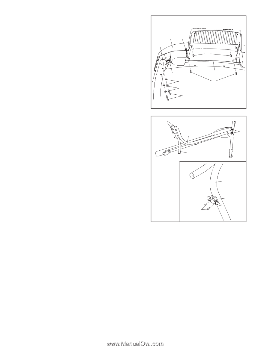
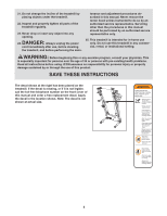
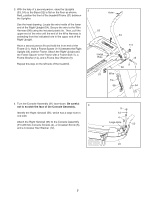
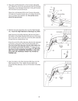
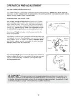
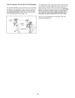
8. Set the Console Assembly (91) on the Right Upright (54) and the Left Upright (not shown). Next, start four Handrail Bolts (3) with four Handrail Washers (13) and four Handrail Star Washers (10) (only two of each are shown) into the Right Upright and the Left Upright. Then, tighten all four Handrail Bolts. Insert the slack in the Wire Harness (98) down into the Right Upright (54). Attach the Console Back (93) to the Console Assembly (91) with four Console Back Screws (7). Make sure that the Wire Harness (98) is in the indicated slot in the Console Back and that no wires are pinched. 8 91 Slot 54 98 10 13 3 7 93 7 9. Carefully lower the Handrails (55, 56) to the floor. Center 9 the Frame (51) between the Handrails, and tighten the four Upright Bolts (2). Then, raise the Handrails back to the vertical position. See the inset drawing. Attach the Latch Assembly (108) to the Left Upright (53) with two Latch Screws (7). Make sure that the Latch Assembly is oriented as shown. See HOW TO CHANGE THE INCLINE OF THE TREADMILL on page 14. Adjust the incline of the treadmill as desired. 51 2 55, 56 53 108 7 10.Make sure that all parts are properly tightened before you use the treadmill. Note: Extra hardware may be included. Keep the included hex keys in a secure place; the large hex key is used to adjust the walking belt (see page 18). To protect the floor or carpet, place a mat under the treadmill. 9
-
 1
1 -
2
-
3
-
 4
4 -
 5
5 -
 6
6 -
 7
7 -
 8
8 -
 9
9 -
 10
10 -
 11
11 -
 12
12 -
 13
13 -
 14
14 -
15
-
16
-
17
-
18
-
19
-
20
-
21
-
22
-
23
 |
 |