Weslo Eclipse 2 Instruction Manual - Page 6
How To Adjust The Drive Belt
 |
View all Weslo Eclipse 2 manuals
Add to My Manuals
Save this manual to your list of manuals |
Page 6 highlights
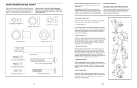
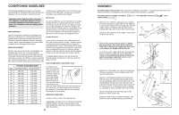
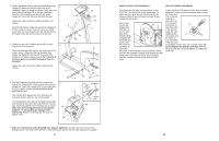
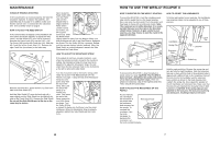
4. Slide a Handlebar Spacer (46) onto the left axle on the 4 Upright (2). Make sure that the open side of the Handlebar Spacer is facing the Upright. Make sure that there are two Bushings (39) in the Left Handlebar. Slide the Left Handlebar onto the left axle on the Upright (2). Tap a 5/8" Axle Cap (43) onto the axle. Repeat this step to attach the Right Handlebar (not shown). 6 Feed the Resistance Cable (33) up into the Upright (2) to form a loop as shown. Insert the tab on the Cable Cover (53) into the indicated slot in the Upright. Attach the Cable Cover with an M4 x 16mm Screw (42). 5. Tighten the three M4 x 16mm Screws (42) on each side of the Side Shield (27). Press two Bushings (39) into the Left Pedal Leg (3) as shown. Insert a Pedal Bolt (8) into the Pedal Leg. Tighten the Pedal Bolt into the left Crank Arm (10). Tighten a 1/2" Nylon Locknut (9) onto the Pedal Bolt. If the these parts are not tight the product may be damaged. Repeat this step to attach the Right Pedal Leg (not shown). 43 5 3 6. Plug the Extension Wire (49) into the socket in the back of the Console (52). Feed the wire down into the 6 Upright (2). Attach the Console (52) to the Upright with four M4 x 18mm Screws (69). Be careful to avoid pinching the wire. The Console (52) requires two 1,5V batteries (not included). Alkaline batteries are recommended. To install batteries, first slide up the Battery Cover (60) and carefully remove the battery clip from the Console (52). Insert two batteries into the battery clip as shown. Make sure that the negative ends of the batteries (marked "-") are touching the springs in the battery clip. Replace the battery clip and close the Battery Cover. 49 69 2 Loop Slot 33 53 42 2 46 39 27 9 10 39 8 42 60 Batteries 52 Battery 52 Clip 69 7. Make sure that all parts of the ECLIPSE II are properly tightened. To protect the floor or carpet from damage, place a mat under the ECLIPSE II. Note: Some parts may be left over after assembly is complete. 6 HOW TO ADJUST THE DRIVE BELT HOW TO TIGHTEN THE CRANK If the Drive Belt (32) slips as you exercise on the ECLIPSE II, the Drive Belt should be adjusted. To adjust the Drive Belt, the side shield must first be removed. Refer to the instructions on page 10 and remove the side shield. Next, loosen the two M8 Flange Nuts 20 32 (23) (there is 26 one on each side of the Flywheel [20]). To tighten the 23 Drive Belt (32), turn the two M6 Nuts (26) clockwise; to loosen the Drive Belt, turn the M6 Nuts counterclockwise. Make sure that the Flywheel is straight and retighten the M8 Flange Nuts (23). When the Drive Belt is properly adjusted, reattach the Side Shield and the Crank Arms. If the Crank Arms (10) become loose, they should be tightened in order to prevent excessive wear. Loosen the Crank Nut (17) on the left Crank Arm. Place the end of a standard 15 screwdriver in one of the slots in the Slotted Crank Nut (15). Lightly tap the 17 screwdriver with a hammer to turn the Slotted Crank Nut coun- terclockwise until the arms are no longer loose. Do not overtighten the Slotted Crank Nut. When the Slotted Crank Nut is properly tightened, retighten the Crank Nut. 11
-
 1
1 -
 2
2 -
 3
3 -
 4
4 -
 5
5 -
 6
6 -
 7
7 -
 8
8
 |
 |
