Weslo Pursuit 2.0ds Bike English Manual - Page 4
Assembly
 |
View all Weslo Pursuit 2.0ds Bike manuals
Add to My Manuals
Save this manual to your list of manuals |
Page 4 highlights
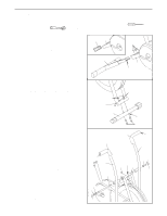
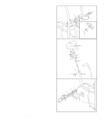
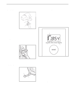
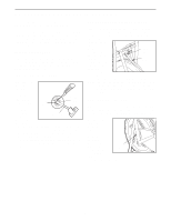
ASSEMBLY Place all parts of the exercise cycle in a cleared area and remove the packing materials. Do not dispose of the packing materials until assembly is completed. Assembly requires a phillips screwdriver and an adjustable wrench (not included). A small amount of liquid soap is also required. 1. Refer to the inset drawing. Remove the Shipping Insert (54) from the Frame (1) and discard it. Turn the Rear Stabilizer (2) so that the slot is down, and insert the Rear Stabilizer into the Frame (1). Attach the Rear Stabilizer with four M5 x 10mm Machine Screws (32). 1 54 1 2 32 1 Slot 2. Align the Front Stabilizer (5) with the saddle bracket 2 on the front of the Frame (1). Make sure that the Front Stabilizer is turned so the square holes are facing away from the saddle bracket. Attach the Front Stabilizer with two M8 x 40mm Carriage Bolts (18), two M8 Curved Washers (14), and two M8 Nylon Locknuts (9). 3. Remove all parts from the Pivot Axle (3). Insert the Pivot Axle into the Frame (1). Align the hole in the center of the Pivot Axle with the hole in the center of the Frame. Tighten an M5 x 10mm Machine Screw (32) into the Frame and the Pivot Axle. Slide the Left and Right Handlebars (40, 41) onto the ends of the Pivot Axle (3). Slide an M8 Flat Washer (38) onto each end of the Pivot Axle, and then thread an M8 Nylon Locknut (9) onto each end of the Pivot Axle. Tighten each Nylon Locknut until at least two threads on the end of the Pivot Axle extend past the Nylon Locknut. Make sure that the Handlebars move freely. Press a Pivot Endcap (50) onto each end of the Pivot Axle (3). Apply a small amount of liquid soap to the upper end of each Handlebar (40, 41). Slide a Foam Grip (42) onto each Handlebar. Make sure that there is a Handlebar Endcap (55) in each Handlebar. 3 55 38 9 50 4 9 1 5 42 41 3 14 Square Holes 18 42 55 40 32 Hole 1 38 9 50
-
 1
1 -
 2
2 -
 3
3 -
 4
4 -
 5
5 -
 6
6 -
 7
7 -
 8
8 -
 9
9 -
 10
10 -
11
-
12
 |
 |