Weslo Pursuit 610 S Bike English Manual - Page 8
Strap Clamp.
 |
View all Weslo Pursuit 610 S Bike manuals
Add to My Manuals
Save this manual to your list of manuals |
Page 8 highlights
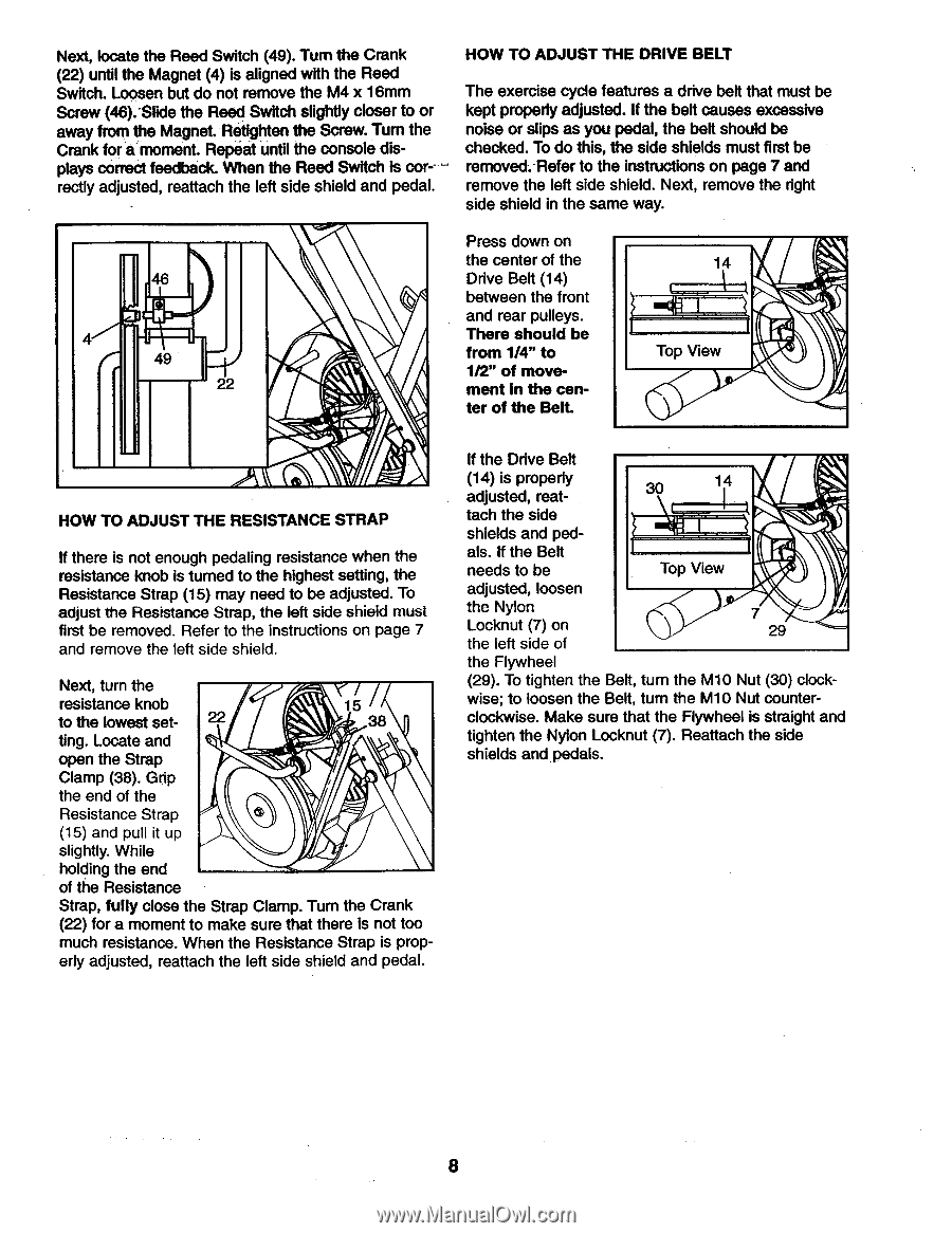
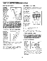
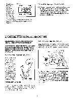
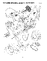
Next, locate the Reed Switch (49). Turn the Crank (22) until the Magnet (4) is aligned with the Reed Switch. Loosen but do not remove the M4 x 16mm Screw (46). Slide the Reed Switch slightly closer to or away from the Magnet. Retighten the Screw. Turn the Crank for a moment. Repeat until the console displays correct feedback. When the Reed Switch is correctly adjusted, reattach the left side shield and pedal. HOW TO ADJUST THE DRIVE BELT The exercise cycle features a drive belt that must be kept properly adjusted. If the belt causes excessive noise or slips as you pedal, the belt should be checked. To do this, the side shields must first be removed.-Refer to the instructions on page 7 and remove the left side shield. Next, remove the right side shield in the same way. 4 49 Press down on the center of the Drive Belt (14) between the front and rear pulleys. There should be from 1/4" to 1/2" of movement in the center of the Belt. 14 Top View HOW TO ADJUST THE RESISTANCE STRAP If there is not enough pedaling resistance when the resistance knob is turned to the highest setting, the Resistance Strap (15) may need to be adjusted. To adjust the Resistance Strap, the left side shield must first be removed. Refer to the instructions on page 7 and remove the left side shield. Next, turn the / resistance knob 15 to the lowest set- 38 ting. Locate and open the Strap Clamp (38). Grip the end of the Resistance Strap (15) and pull it up slightly. While holding the end of the Resistance Strap, fully close the Strap Clamp. Turn the Crank (22) for a moment to make sure that there is not too much resistance. When the Resistance Strap is prop- erly adjusted, reattach the left side shield and pedal. If the Drive Belt '.1 (14) is properly adjusted, reat- 30 14 tach the side shields and ped- als. If the Belt needs to be Top View adjusted, loosen the Nylon Locknut (7) on the left side of 7 29 the Flywheel (29). To tighten the Belt, turn the M10 Nut (30) clock- wise; to loosen the Belt, turn the M10 Nut counter- clockwise. Make sure that the Flywheel is straight and tighten the Nylon Locknut (7). Reattach the side shields and pedals. 8
-
 1
1 -
2
-
 3
3 -
 4
4 -
 5
5 -
 6
6 -
 7
7 -
 8
8 -
 9
9 -
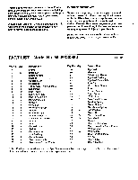 10
10 -
 11
11 -
 12
12
 |
 |