Westinghouse MT10 FLIP Installation Instructions - Page 2
pattern. For safe mounting, please make sure that mounting screws turn at least - top
 |
UPC - 882777610015
View all Westinghouse MT10 FLIP manuals
Add to My Manuals
Save this manual to your list of manuals |
Page 2 highlights
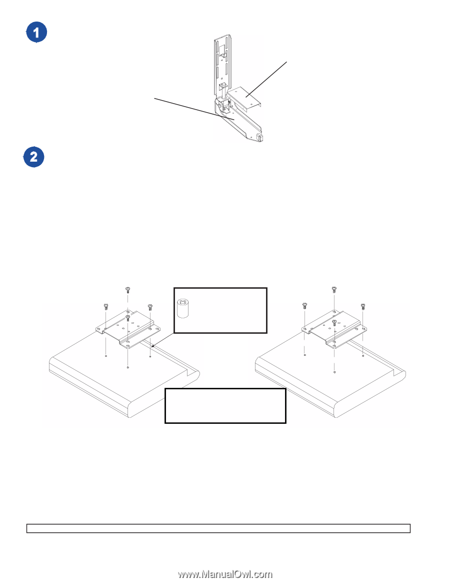
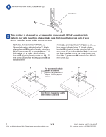
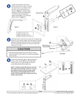
Remove cord cover from LCD assembly (A). A Cord Cover This product is designed to accommodate screens with VESA® compliant hole pattern. For safe mounting, please make sure that mounting screws turn at least three complete turns in the screen inserts. FOR VESA 75 MOUNTING PATTERN: 1.) Choose hole pattern indicated below. 2.) Attach adapter bracket (B) to back of monitor using four M4 x 10 mm screws (C) as indicated below. 3.) If hole pattern is in a pocket, attach adapter bracket (B) to back of monitor using four M4 x 20 mm screws (O) and four retaining spacers (N) as indicated below. FOR VESA 100 MOUNTING PATTERN: 1.) Choose hole pattern indicated below. 2.) Attach adapter bracket (B) to back of monitor using four M4 x 10 mm screws (C) as indicated below. Note: If you don't get three complete turns in the screen inserts, use four M4 x 12 mm screws (M) instead of four M4 x 10 mm screws (C). For screens with a hole pattern in a pocket, spacers (N) go between adapter bracket (B) and screen. B B Note: Screen may appear slightly different than illustrated 2 of 5 Visit the Westinghouse Web Site at www.westinghousedigital.com ISSUED: 04-16-04 SHEET #: 090-9101-1 For customer service call 1-866-287-5555.
-
 1
1 -
 2
2 -
 3
3 -
 4
4 -
 5
5
 |
 |