Westinghouse VR5535Z User Manual - Page 6
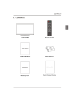
Main accessories, Installation Steps
 |
View all Westinghouse VR5535Z manuals
Add to My Manuals
Save this manual to your list of manuals |
Page 6 highlights
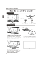
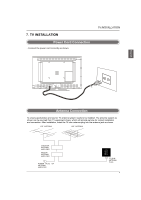
Main accessories: Stand Support Installation Steps: 1 Main Unit Base Stand Screw Screw (MPW4 x 20,4pcs) (TP4 x 20A-HO,2pcs) 2 Take out the main unit and the base stand from the carton, Unscrew the 6 screws (4PCS MPW4 x 12 / 2PCS TP4 x 20A-HO) to remove the stand support from the main unit. 3 Connect the stand support and the base stand with 4PCS of MPW4 x 20 screws. Screw back the 6 screws which were removed from step1 (4PCS MPW4 x 12 / 2PCS TP4 x 20A-HO) to connect the main unit and the stand support.
-
 1
1 -
 2
2 -
 3
3 -
 4
4 -
 5
5 -
 6
6 -
 7
7 -
 8
8 -
 9
9 -
 10
10 -
 11
11 -
 12
12 -
13
-
14
-
15
-
16
-
17
-
18
-
19
-
20
-
21
-
22
-
23
-
24
-
25
-
26
-
27
-
28
-
29
-
30
 |
 |
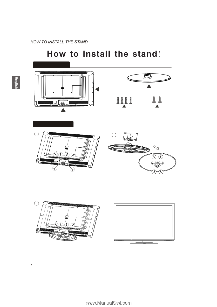
Main Unit
Base Stand
Stand Support
Take out the main unit and the base stand
from the carton, Unscrew the 6 screws
(4
MPW4 x 12 / 2
)
to remove the stand support from the
main unit.
PCS
PCS TP4 x 20A-HO
Screw back the 6 screws which were
removed from step1 (4
MPW4 x 12 /
2
)
to connect
the
main unit and the stand support.
PCS
PCS
TP4 x 20A-HO
Connect the stand support and the base
stand
with 4PCS of MPW4 x 20 screws.
Main accessories:
Screw
(MPW4 x 20,4pcs)
Installation Steps:
Screw
(
)
TP4 x 20A-HO,2pcs
1
2
3