Whirlpool GI15NDXZB Installation Guide - Page 8
Ice Maker Door Reversal-Side Swing Only
 |
View all Whirlpool GI15NDXZB manuals
Add to My Manuals
Save this manual to your list of manuals |
Page 8 highlights
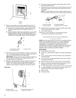
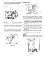
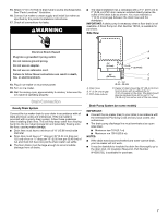
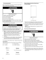
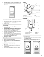
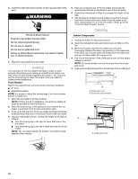
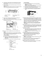
Connecting the Drain After ensuring that the drain system is adequate, follow these steps to properly place the ice maker: WARNING Remove Stainless Steel Door Wrap Panel- On Some Models Electrical Shock Hazard Plug into a grounded 3 prong outlet. Do not remove ground prong. Do not use an adapter. Do not use an extension cord. Failure to follow these instructions can result in death, fire, or electrical shock. 1. Plug into a grounded 3 prong outlet. WARNING Excessive Weight Hazard Use two or more people to move and install ice maker. Failure to do so can result in back or other injury. A A. Hex-head screws 1. Remove the 2 hex-head screws located under the stainless steel door wrap panel flange on the bottom of the door. 2. Pull up and outward on the door wrap panel from the bottom. 3. Rotate the door wrap panel until it separates from the door and pull up. NOTE: Be sure the edge guards do not separate from the door wrap panel. Door Stop and End-Cap Reversal 2. Style 1-For gravity drain system, push the ice maker into position so that the ice maker drain tube is positioned over the PVC drain reducer. See "Gravity Drain System." Style 2-For drain pump system connect the drain pump outlet hose to the drain. See "Drain Pump System." 3. Recheck the ice maker to be sure that it is level. See "Leveling." 4. If it is required by your local sanitation code, seal the cabinet to the floor with an approved caulking compound after all water and electrical connections have been made. Ice Maker Door Reversal-Side Swing Only Tools Needed Gather the required tools and parts before starting installation. wrench ■ Flat putty knife wrench ■ Phillips screwdriver Hinge pin hex-head hinge screw WARNING Electrical Shock Hazard Disconnect power before servicing. Replace all parts and panels before operating. Failure to do so can result in death or electrical shock. 1. Unplug the ice maker or disconnect power. 2. Remove the handle screws and handle (on some models). 3. Remove the hinge pin from the top hinge. 4. Remove the door from the hinges and replace the top hinge pin. 5. Remove the screw and door stop at corner A. Remove the screw and end cap at corner C. Place the door stop at corner C, and tighten screw. Place the end cap at corner A, and tighten screw. Handle screw End cap screw 8
-
 1
1 -
2
-
 3
3 -
 4
4 -
 5
5 -
 6
6 -
 7
7 -
 8
8 -
 9
9 -
 10
10 -
 11
11 -
 12
12 -
 13
13 -
14
-
15
-
16
-
17
-
18
-
19
-
20
-
21
-
22
-
23
-
24
 |
 |