Whirlpool GI15NDXZS Installation Guide - Page 2
Installation Instructions - ice maker
 |
View all Whirlpool GI15NDXZS manuals
Add to My Manuals
Save this manual to your list of manuals |
Page 2 highlights
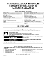
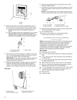
State of California Proposition 65 Warnings: WARNING: This product contains one or more chemicals known to the State of California to cause cancer. WARNING: This product contains one or more chemicals known to the State of California to cause birth defects or other reproductive harm. INSTALLATION INSTRUCTIONS Unpack the Ice Maker WARNING Excessive Weight Hazard Use two or more people to move and install ice maker. Failure to do so can result in back or other injury. Removing Packaging Materials Remove tape and glue from your ice maker before using. ■ To remove any remaining tape or glue from the exterior of the ice maker, rub the area briskly with your thumb. Tape or glue residue can also be easily removed by rubbing a small amount of liquid dish soap over the adhesive with your fingers. Wipe with warm water and dry. ■ Do not use sharp instruments, rubbing alcohol, flammable fluids, or abrasive cleaners to remove tape or glue. Do not use chlorine bleach on the stainless steel surfaces of the ice maker. These products can damage the surface of your ice maker. Cleaning Before Use After you remove all of the packaging materials, clean the inside of your ice maker before using it. See the cleaning instructions in the "Ice Maker Care" section. Location Requirements ■ To ensure proper ventilation for your ice maker, the front side must be completely unobstructed. The ice maker may be closed-in on the top and three sides, but the installation should allow the ice maker to be pulled forward for servicing if necessary. ■ Installation of the ice maker requires a cold water supply inlet of ¹⁄₄" (6.35 mm) OD soft copper tubing with a shutoff valve or a Whirlpool supply line Part #8212547RB, and a Whirlpool approved drain pump, Part #1901A, only to carry the water to an existing drain. ■ Choose a well ventilated area with temperatures above 55°F (13°C) and below 110°F (43°C). Best results are obtained between 70°F and 90°F (21ºC and 32°C). ■ The ice maker must be installed in an area sheltered from the elements, such as wind, rain, water spray, or drip. ■ When installing the ice maker under a counter, follow the recommended opening dimensions shown. Place electrical and plumbing fixtures in the recommended location as shown. NOTES: ■ Check that the power supply cord is not damaged, or pinched or kinked between the ice maker and the cabinet. ■ Check that the water supply line is not damaged, or pinched or kinked between the ice maker and the cabinet. ■ Check that the drain line (on some models) is not damaged, or pinched or kinked between the ice maker and the cabinet. 34" (86.4 cm) Min. 34¹⁄₂" (87.6 cm) Max. 11¹⁄₂" (29.2 cm) 3¹⁄₂" (8.9 cm) 9" (22.9 cm) 24" (60.1 cm) A 28¹⁄₂" (72.4 cm) B 15" (38.1 cm) A. Recommended location for electrical and plumbing fixtures B. Floor level ■ Choose a location where the floor is even. It is important for the ice maker to be level in order to work properly. If needed, you can adjust the height of the ice maker by changing the height of the leveling legs. See "Leveling." 2
-
 1
1 -
 2
2 -
 3
3 -
 4
4 -
 5
5 -
 6
6 -
 7
7 -
 8
8 -
9
-
10
-
11
-
12
-
13
-
14
-
15
-
16
-
17
-
18
-
19
-
20
-
21
-
22
-
23
-
24
 |
 |