Whirlpool GSC25C4EYB Installation Guide - Page 2
Refrigerator Safety, Installation Requirements
 |
View all Whirlpool GSC25C4EYB manuals
Add to My Manuals
Save this manual to your list of manuals |
Page 2 highlights
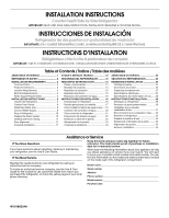
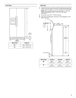
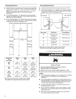
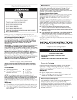
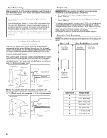
REFRIGERATOR SAFETY Your safety and the safety of others are very important. We have provided many important safety messages in this manual and on your appliance. Always read and obey all safety messages. This is the safety alert symbol. This symbol alerts you to potential hazards that can kill or hurt you and others. All safety messages will follow the safety alert symbol and either the word "DANGER" or "WARNING." These words mean: DANGER You can be killed or seriously injured if you don't immediately follow instructions. WARNING You can be killed or seriously injured if you don't follow instructions. All safety messages will tell you what the potential hazard is, tell you how to reduce the chance of injury, and tell you what can happen if the instructions are not followed. INSTALLATION REQUIREMENTS Tools and Parts IMPORTANT: ■ Observe all governing codes and ordinances. ■ Installer: Leave Installation Instructions with homeowner. ■ Homeowner: Keep Installation Instructions for future reference and for the local electrical inspector's use. ■ Keep cardboard shipping piece or plywood under refrigerator until it is installed in the operating position. ■ Comply with installation specifications and dimensions. ■ Remove any moldings or decorative panels from kitchen cabinets that would not allow access to the refrigerator for service. ■ Contact a qualified electrical installer. TOOLS NEEDED (on some models): Gather the required tools and parts before starting installation. Read and follow the instructions provided with any tools listed here. ■ Cordless drill or adjustable wrench Nut driver and drill bit ■ Flat-blade screwdriver and ¹⁄₂" Open-end wrenches ■ Two adjustable wrenches and ¹⁄₂" Socket wrenches PARTS NEEDED (on some models): ■ Your refrigerator dealer has a kit available with a ¹⁄₄" (6.35 mm) saddle-type shutoff valve, a union, and copper tubing. ■ Or you can purchase a ¹⁄₄" (6.35 mm) copper tubing with shutoff valve and a ¹⁄₄" (6.35 mm) compression fitting (coupling). ■ Depending on water line connections, you may also need a ¹⁄₄" (6.35 mm) nut and ¹⁄₄" (6.35 mm) ferrule. Top View Product Dimensions 35¹⁄₂" (90.0 cm) ⁵⁄₈" (1.6 cm) 23⁷⁄₈" (60.4 cm) AC 15³⁄₈" 20" (38.9 cm) (50.8 cm) B Door Style Depth A Depth B Depth C Flat 27¹⁄₂" 2⁵⁄₈" (6.5 cm) 30" (76.3 cm) (69.8 cm) maximum* maximum* Curved 28⁵⁄₈" (72.5 cm) 2⁵⁄₈" (6.5 cm) 31¹⁄₈" (79.1 cm) *Dimension may vary based on style of door handle. The depth for the largest available handle is listed. 2
-
 1
1 -
 2
2 -
 3
3 -
 4
4 -
 5
5 -
 6
6 -
 7
7 -
 8
8 -
9
-
10
-
11
-
12
-
13
-
14
-
15
-
16
-
17
-
18
-
19
-
20
-
21
-
22
-
23
-
24
-
25
-
26
-
27
-
28
-
29
-
30
-
31
-
32
-
33
-
34
-
35
-
36
 |
 |
