Whirlpool GXU7130DXB Installation Guide - Page 4
Installation Requirements - parts
 |
View all Whirlpool GXU7130DXB manuals
Add to My Manuals
Save this manual to your list of manuals |
Page 4 highlights
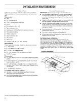
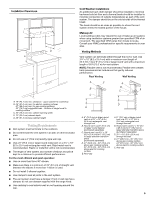
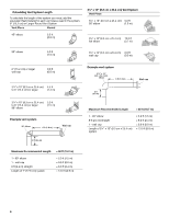
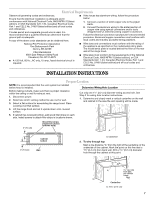
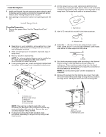
INSTALLATION REQUIREMENTS Tools and Parts Gather the required tools and parts before starting installation. Read and follow the instructions provided with any tools listed here. Tools needed ■ Drill ■ 1¹⁄₄" (3.0 cm) drill bit 3.0 mm) drill bit for pilot holes ■ Pencil ■ Wire stripper or utility knife ■ Tape measure or ruler ■ Caulking gun and weatherproof caulking compound ■ Flat-blade screwdriver ■ Phillips screwdriver ■ Saber or keyhole saw ■ Vent clamps ■ Metal snips ■ Compass or 8" (20.3 cm) circle template Parts supplied Remove parts from package. Check that all parts are included. ■ 2 - Metal filters ■ 6 - 3.5 x 9.5 mm mounting screws ■ 3 - 4.5 x 13 mm damper screws ■ 3¹⁄₄" x 10" (8.3 x 25.4 cm) damper/vent connector ■ T-20 Torx®† adapter Parts needed ■ 3¹⁄₄" x 10" (8.3 x 25.4 cm) or 6" (15.2 cm) or larger round metal venting ■ 6" (15.2 cm) or larger round damper, if using 6" (15.2 cm) or larger round vent system ■ 3¹⁄₄" x 10" (8.3 x 25.4 cm) to 6" (15.2 cm) or larger diameter transition piece if using 6" (15.2 cm) or larger diameter round vent system. ■ 3 - UL listed wire connectors For cabinets with recessed bottoms: ■ Two 2" (5.1 cm) wide filler strips. Length and thickness determined by recess dimensions. ■ Four flat head wood screws or machine screws with washers and nuts (to attach filler strips). Location Requirements IMPORTANT: Observe all governing codes and ordinances. ■ It is the installer's responsibility to comply with installation clearances specified on the model/serial rating plate. The model/serial rating plate is located inside the range hood on the left wall. ■ Range hood location should be away from strong draft areas, such as windows, doors and strong heating vents. ■ Cabinet opening dimensions that are shown must be used. Given dimensions provide minimum clearance. Consult the cooktop/range manufacturer installation instructions before making any cutouts. ■ Grounded electrical outlet is required. See "Electrical Requirements" section. ■ The hood is factory-set for vented installations. ■ All openings in ceiling and wall where range hood will be installed must be sealed. For Mobile Home Installations The installation of this range hood must conform to the Manufactured Home Construction Safety Standards, Title 24 CFR, Part 328 (formerly the Federal Standard for Mobile Home Construction and Safety, title 24, HUD, Part 280) or when such standard is not applicable, the standard for Manufactured Home Installation 1982 (Manufactured Home Sites, Communities and Setups) ANSI A225.1/NFPA 501A*, or latest edition, or with local codes. Product Dimensions 1³⁄₄" (4.4 cm) 4³⁄₄" (12.1 cm) 4 10.3 cm) 1" (2.5 cm) ³⁄₄" (2.0 cm) 29 76.0 cm) 9" (22.9 cm) 1¹⁄₂" (3.8 cm) 20" (50.8 cm) †®TORX is a registered trademark of Acument Intellectual Properties, LLC 4
-
 1
1 -
 2
2 -
 3
3 -
 4
4 -
 5
5 -
 6
6 -
 7
7 -
 8
8 -
 9
9 -
 10
10 -
11
-
12
-
13
-
14
-
15
-
16
-
17
-
18
-
19
-
20
-
21
-
22
-
23
-
24
-
25
-
26
-
27
-
28
 |
 |