Whirlpool GXW7336DXS Use & Care Guide - Page 6
Electrical Requirements - range hood
 |
View all Whirlpool GXW7336DXS manuals
Add to My Manuals
Save this manual to your list of manuals |
Page 6 highlights
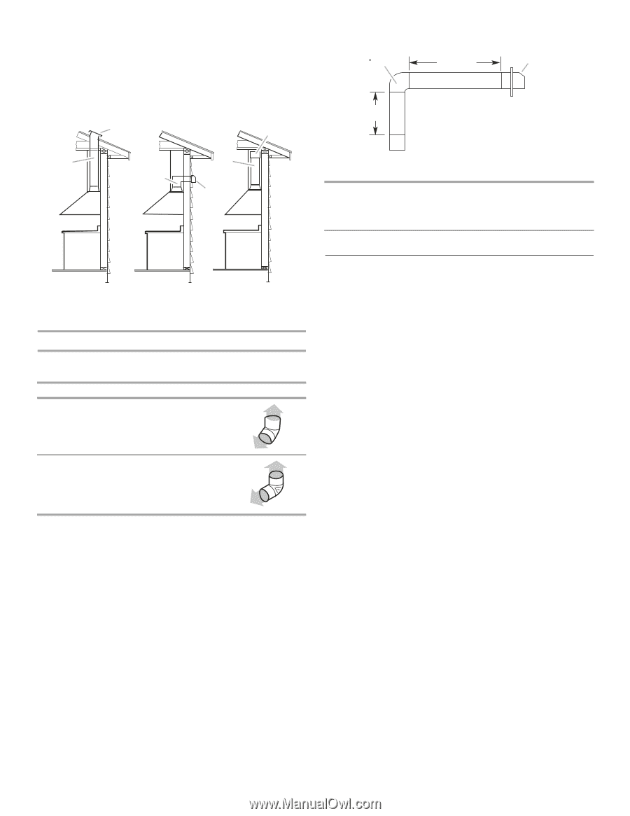
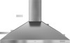
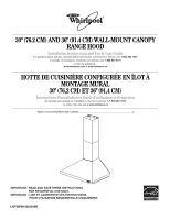
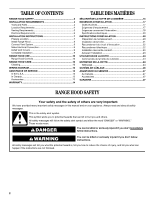
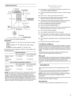
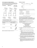
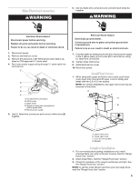
For Non-Vented (recirculating) Installations If it is not possible to vent cooking fumes and vapors to the outside, the hood can be used in the non-vented (recirculating) version, fitting a charcoal filter and the deflector. Fumes and vapors are recycled through the top grille. Roof Venting Wall Venting Non-vented (recirculating) A A B B B A A. Roof cap B. 6" (15.2 cm) round vent A. Wall cap B. 6" (15.2 cm) round vent A. Deflector B. 6" (15.2 cm) round vent Calculating Vent System Length To calculate the length of the system you need, add the equivalent feet (meters) for each vent piece used in the system. Vent Piece 6" (15.2 cm) Round 45° elbow 2.5 ft (0.8 m) 90° elbow 5.0 ft (1.5 m) Maximum equivalent vent length is 35 ft (10.7 m). Example vent system 90 elbow 6 ft (1.8 m) Wall cap 2 ft (0.6 m) The following example falls within the maximum recommended vent length of 35 ft (10.7 m). 1 - 90° elbow 1 - wall cap = 5.0 ft (1.5 m) = 0.0 ft (0.0 m) 8 ft (2.4 m) straight = 8.0 ft (2.4 m) Length of system = 13.0 ft (3.9 m) Electrical Requirements Observe all governing codes and ordinances. Ensure that the electrical installation is adequate and in conformance with National Electrical Code, ANSI/NFPA 70 (latest edition), or CSA Standards C22.1-94, Canadian Electrical Code, Part 1 and C22.2 No. 0-M91 (latest edition) and all local codes and ordinances. If codes permit and a separate ground wire is used, it is recommended that a qualified electrician determine that the ground path is adequate. A copy of the above code standards can be obtained from: National Fire Protection Association One Batterymarch Park Quincy, MA 02269 CSA International 8501 East Pleasant Valley Road Cleveland, OH 44131-5575 ■ A 120 volt, 60 Hz., AC only, 15-amp, fused electrical circuit is required. ■ If the house has aluminum wiring, follow the procedure below: 1. Connect a section of solid copper wire to the pigtail leads. 2. Connect the aluminum wiring to the added section of copper wire using special connectors and/or tools designed and UL listed for joining copper to aluminum. Follow the electrical connector manufacturer's recommended procedure. Aluminum/copper connection must conform with local codes and industry accepted wiring practices. ■ Wire sizes and connections must conform with the rating of the appliance as specified on the model/serial rating plate. The model/serial plate is located behind the filter on the rear wall of the range hood. ■ Wire sizes must conform to the requirements of the National Electrical Code, ANSI/NFPA 70 (latest edition), or CSA Standards C22. 1-94, Canadian Electrical Code, Part 1 and C22.2 No. 0-M91 (latest edition) and all local codes and ordinances. 6
-
 1
1 -
 2
2 -
 3
3 -
 4
4 -
 5
5 -
 6
6 -
 7
7 -
 8
8 -
 9
9 -
 10
10 -
 11
11 -
 12
12 -
13
-
14
-
15
-
16
-
17
-
18
-
19
-
20
-
21
-
22
-
23
-
24
-
25
-
26
-
27
-
28
 |
 |