Whirlpool GY397LXUQ Installation Instructions - Page 12
Verify Anti-Tip Bracket Location, Level Range
 |
View all Whirlpool GY397LXUQ manuals
Add to My Manuals
Save this manual to your list of manuals |
Page 12 highlights
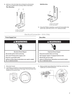
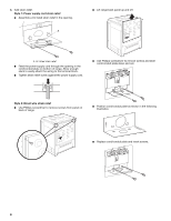
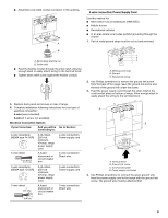
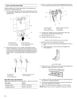
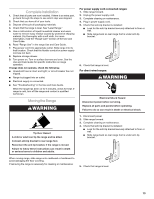
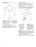
3-wire connection: Direct Wire Use this method only if local codes permit connecting ground conductor to neutral supply wire. 1. Pull the conduit through the hole and conduit plate on bottom of range. Allow enough slack to easily attach the wiring to the terminal block. A 3. Use ³⁄₈" nut driver to connect the bare (green) ground wire to the center terminal block post with one of the 10-32 hex nuts. F A E B B C D FE A. Terminal block B. Ground-link screw C. Cord/conduit plate D. Line 2 (red) wire E. Bare (green) ground wire F. Line 1 (black) wire 2. Attach terminal lugs to line 1 (black), bare (green) ground, and line 2 (red) wires. Loosen (do not remove) the set screw on the front of the terminal lug and insert exposed wire end through bottom of terminal lugs. Securely tighten set screw to torque shown in following Bare Wire Torque Specifications chart. A D C A. 10-32 hex nut B. Line 1 (black) C. Ground-link screw D. Bare (green) ground wire E. Line 2 (red) F. Terminal lug 4. Connect line 1 (black) and line 2 (red) wires to the outer terminal block posts with 10-32 hex nuts. 5. Securely tighten hex nuts. 6. Replace terminal block access cover. Verify Anti-Tip Bracket Location 1. Making sure the anti-tip bracket is installed: ■ Look for the anti-tip bracket securely attached to floor or wall. ■ Slide range back so rear range foot is engaged with anti-tip bracket. B C D E Level Range 1. Place rack in oven. Place level on rack and check levelness of range, first side to side; then front to back. A. Terminal lug B. Set screw C. Line 1 (black) wire D. Bare (green) ground wire E. Line 2 (red) wire Bare Wire Torque Specifications Attaching terminal lugs to the terminal block - 20 lbs-in. (2.3 N-m) Wire Awg Torque 8 gauge copper 6 gauge aluminum 25 lbs-in. (2.8 N-m) 35 lbs-in. (4.0 N-m) 2. If range is not level, pull range forward until rear leveling leg is removed from the anti-tip bracket. 3. Use wrench to adjust leveling legs up or down until range is level. Push range back into position. 4. Check that rear leveling leg is engaged in anti-tip bracket. NOTE: Range must be level for satisfactory baking conditions. 12
-
 1
1 -
2
-
3
-
4
-
5
-
6
-
 7
7 -
 8
8 -
 9
9 -
 10
10 -
 11
11 -
 12
12 -
 13
13 -
 14
14 -
 15
15 -
 16
16 -
 17
17 -
18
-
19
-
20
 |
 |
