Whirlpool LER8648PW Installation Instructions - Page 11
Whirlpool LER8648PW Manual
 |
View all Whirlpool LER8648PW manuals
Add to My Manuals
Save this manual to your list of manuals |
Page 11 highlights
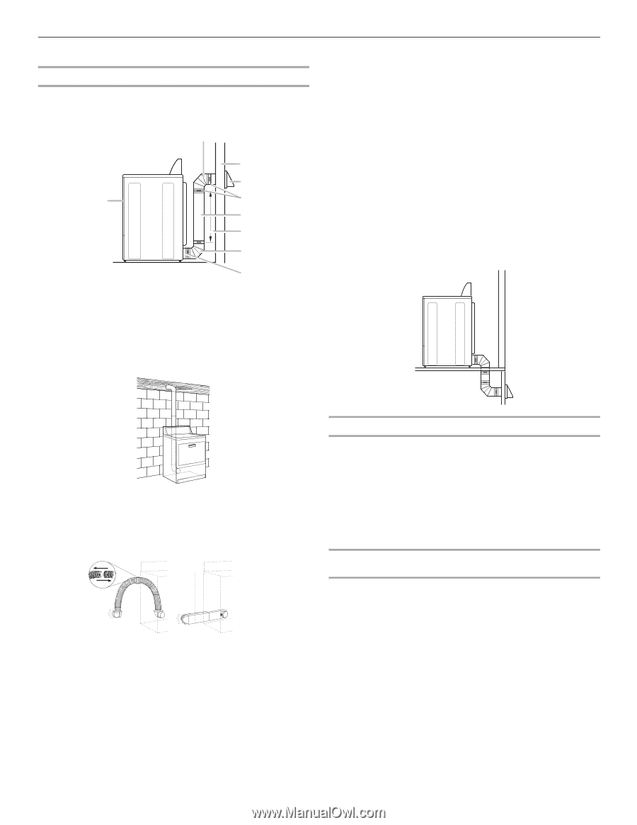
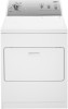
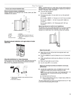
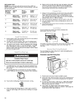
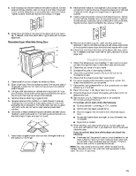
Plan Vent System Choose your exhaust installation type Recommended exhaust installations Typical installations vent the dryer from the rear of the dryer. Other installations are possible. NOTE: The following kits for close clearance alternate installations are available for purchase. Please see the "Assistance or Service" section of the Dryer User Instructions. s Over-the-Top Installation: Part Number 4396028 s B C D A E F G B H A. Dryer B. Elbow C. Wall D. Exhaust hood E. Clamps F. Rigid metal or flexible metal vent G. Vent length necessary to connect elbows H. Exhaust outlet Periscope Installation (For use with dryer vent to wall vent mismatch): Part Number 4396037 - 0" (0 cm) to 18" (45.72 cm) mismatch Part Number 4396011 - 18" (45.72 cm) to 29" (73.66 cm) mismatch Part Number 4396014 - 29" (73.66 cm) to 50" (127 cm) mismatch Special provisions for mobile home installations The exhaust vent must be securely fastened to a noncombustible portion of the mobile home structure and must not terminate beneath the mobile home. Terminate the exhaust vent outside. Standard exhaust installation with rigid metal or flexible metal vent Determine vent path s s s Select the route that will provide the straightest and most direct path outdoors. Plan the installation to use the fewest number of elbows and turns. When using elbows or making turns, allow as much room as possible. Bend vent gradually to avoid kinking. Use the fewest 90° turns possible. Determine vent length and elbows needed for best drying performance Alternate installations for close clearances Venting systems come in many varieties. Select the type best for your installation. Two close-clearance installations are shown. Refer to the manufacturer's instructions. s s s Use the Vent system chart below to determine type of vent material and hood combinations acceptable to use. NOTE: Do not use vent runs longer than those specified in the Vent system chart. Exhaust systems longer than those specified will: A B s s Shorten the life of the dryer. Reduce performance, resulting in longer drying times and increased energy usage. A. Over-the-top installation (also available with one offset elbow) B. Periscope installation The Vent system chart provides venting requirements that will help to achieve the best drying performance. 11
-
 1
1 -
2
-
3
-
4
-
5
-
 6
6 -
 7
7 -
 8
8 -
 9
9 -
 10
10 -
 11
11 -
 12
12 -
 13
13 -
 14
14 -
 15
15 -
 16
16 -
17
-
18
-
19
-
20
-
21
-
22
-
23
-
24
-
25
-
26
-
27
-
28
 |
 |