Whirlpool LTE5243DQ Ventilation Specification - Page 5
Venting Requirements - model
 |
UPC - 050946532578
View all Whirlpool LTE5243DQ manuals
Add to My Manuals
Save this manual to your list of manuals |
Page 5 highlights
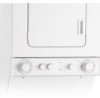
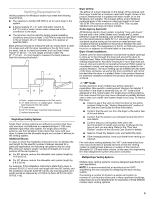
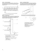
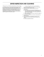
Venting Requirements Venting systems for Whirlpool dryers must meet the following requirements: ■ The capacity to handle 200 CFM of air for each dryer in the system. ■ A back pressure of -1.0" (-25 mm) water column to 0.6" (15 mm) of water column when measured at the connection to the dryer. ■ The minimum duct air velocity during normal operating conditions should be at least 1,100 FPM to keep lint moving in the air stream. (In a 4" diameter pipe, this requires at least 96 CFM.) Back pressure should be measured with an empty dryer, a clean lint screen and with the dryer operating in the Air Only cycle (no heat). Use an inclined manometer, such as Dryer model 102 (0"-2" [0 mm - 51 mm] range) or Dryer model 172 (0"-1" [0 mm - 25 mm] range) to measure the back pressure. See the following illustration. C D B A E A. Dryer - empty and running on Air Only cycle B. 12" (305 mm) min. of straight pipe - measure back pressure from the center C. To vent system D. 0.6" (15 mm) water maximum back pressure E. Inclined manometer Single Dryer Venting Systems Single dryer venting systems are defined as systems that have only one dryer unit attached to a residential-type 4" (102 mm) diameter rigid metal vent system. For single dryer venting systems, see the Installation Instructions that came with your dryer to determine the allowable length and number of elbows for the venting system. Additional Elbows In cases in which the Installation Instructions do not address the vent length for the specific number of elbows required for a particular application, the following calculations may be used. (The total vent system length includes all straight and curved portions of the vent system.): ■ For 90° elbows, reduce the allowable vent system length by 10 ft (3.05 m). ■ For 45° elbows, reduce the allowable vent system length by 6 ft (1.83 m). For example, if the Installation Instructions state that a dryer is allowed 40 ft (12.2 m) of total vent length with two 90° bends, and the installation requires three 90° bends, the total allowable vent length would be reduced by 10 ft (3.0 m) (from 40 ft [12.2 m] to 30 ft [9.1 m]). Dryer Airflow The airflow of a dryer depends on the design of the exhaust vent. Each dryer model has a maximum rated vent length, shown in the product literature that is supplied with each model, or on the Whirlpool.com website. The exhaust airflow of any Whirlpool produced dryer at the maximum rated vent length is at least 100 CFM. The maximum airflow is 200 CFM. This includes standard vent and long vent dryer models. Codes Agency Approvals All Whirlpool electric dryer models, including "long vent dryers," that are sold in the United States and Canada are UL listed (reference UL2158 standard), and all Whirlpool gas dryer models are CSA listed (reference ANSI Z21.5.1 standard). These standards require testing at the maximum-rated exhaust vent conditions that are published in the product literature for each individual model. The designation for the UL or CSA listing can be found on or adjacent to the serial label on the product. Dryer Closet Installations Closets used for dryer installation must provide multiple openings to allow air to flow through the dryer and around the dryer to dissipate heat. Refer to the product literature for details of room venting requirements. Any dryer enclosure or room that does not have an inlet and outlet for an operating forced air HVAC system is considered a closet, and requires room venting as stated in the product literature. The room venting can be installed into the walls of the dryer enclosure, as well as the door, provided it will not be blocked after the dryer is installed. Refer to the product literature for minimum clearances between the product and the enclosure surfaces. "AF" Code Certain electronic dryer models have airflow detection capabilities. (See specific model product literature for details). If the airflow in the dryer is extremely low, an "AF" code will be displayed on the control panel. For single dryer venting systems, this code means that you may have a blocked or partially blocked vent or that your overall vent system length is too long. To resolve this issue: ■ Check to see if the vent run from the dryer to the wall is crushed. Refer to the "Venting Requirements" section of the Use and Care Guide for more information. ■ Confirm that the vent run from the dryer to the wall is free of lint and debris. ■ Confirm that the exterior vent exhaust hood is free of lint and debris. ■ Confirm that your vent system falls within the recommended run length and number of elbows for the type of vent you are using. Refer to the "Plan Vent System" section of the Use and Care Guide for details. ■ Select a Timed Dry heated cycle, and restart the dryer. ■ If the message persists, have your entire home venting run cleaned. For multi-dryer venting systems, the "AF" code means that your vent may be blocked or partially blocked or that the venting system is creating back pressure in excess of the maximum allowable 0.6" (15 mm) water column. In this case, the engineering firm that designed the system should be consulted. Multiple Dryer Venting Systems Multiple dryer venting systems must be designed specifically for each application. NOTE: It is recommended that an architectural or HVAC engineering firm be consulted for designing the dryer venting system. Connecting a number of dryers to a single vent system is common in coin-laundry stores and in many apartment buildings. Listed here are some requirements for examples of three different multiple dryer venting systems. 5
-
 1
1 -
 2
2 -
 3
3 -
 4
4 -
 5
5 -
 6
6 -
 7
7 -
 8
8
 |
 |