Whirlpool MGR8772WS Installation Instructions - Page 4
Installation Requirements
 |
View all Whirlpool MGR8772WS manuals
Add to My Manuals
Save this manual to your list of manuals |
Page 4 highlights
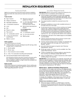
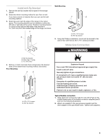
INSTALLATION REQUIREMENTS Tools and Parts Gather the required tools and parts before starting installation. Read and follow the instructions provided with any tools listed here. Tools needed ■ Tape measure ■ Phillips screwdriver ■ Flat-blade screwdriver flat-blade screwdriver ■ Level ■ Drill ■ Wrench or pliers ■ Pipe wrench combination wrench 3.2 mm) drill bit (for wood floors) ■ Marker or pencil ■ Pipe-joint compound resistant to LP gas 4.8 mm) carbide-tipped masonry drill bit (for concrete/ceramic floors) ■ Noncorrosive leak-detection solution For LP/Natural Gas Conversions ■ ½" combination wrench 7.0 mm) nut driver ■ Masking tape Parts supplied Check that all parts are included. ■ LP/Natural Gas Conversion Kit (taped near left rear leg, inside storage drawer compartment) ■ 2 - Burner grates ■ 5 - Burner caps ■ 2 - Oven racks (3 on some models) ■ 2 - #12 x 1⁵⁄₈" screws (for mounting anti-tip bracket) ■ Anti-tip bracket (taped inside storage drawer) Anti-tip bracket must be securely mounted to the back wall or floor. Thickness of flooring may require longer screws to anchor bracket to subfloor. Longer screws are available from your local hardware store. Parts needed Check local codes and consult gas supplier. Check existing gas supply and electrical supply. See "Electrical Requirements" and "Gas Supply Requirements" sections. Location Requirements IMPORTANT: Observe all governing codes and ordinances. Do not obstruct flow of combustion and ventilation air. ■ It is the installer's responsibility to comply with installation clearances specified on the model/serial rating plate. The model/serial rating plate is located behind the storage drawer on the right-hand side of the oven frame. ■ The range should be located for convenient use in the kitchen. ■ Recessed installations must provide complete enclosure of the sides and rear of the range. ■ To eliminate the risk of burns or fire by reaching over heated surface units, cabinet storage space located above the surface units should be avoided. If cabinet storage is to be provided, the risk can be reduced by installing a range hood or microwave hood combination that projects horizontally a minimum of 5" (12.7 cm) beyond the bottom of the cabinets. ■ All openings in the wall or floor where range is to be installed must be sealed. ■ Cabinet opening dimensions that are shown must be used. Given dimensions are minimum clearances. ■ The floor anti-tip bracket must be installed. To install the antitip bracket shipped with the range, see "Install Anti-Tip Bracket" section. ■ Grounded electrical supply is required. See "Electrical Requirements" section. ■ Proper gas supply connection must be available. See "Gas Supply Requirements" section. ■ Contact a qualified floor covering installer to check that the floor covering can withstand at least 200°F (93°C). ■ Use an insulated pad or ¼" (0.64 cm) plywood under range if installing range over carpeting. IMPORTANT: To avoid damage to your cabinets, check with your builder or cabinet supplier to make sure that the materials used will not discolor, delaminate or sustain other damage. This oven has been designed in accordance with the requirements of UL and CSA International and complies with the maximum allowable wood cabinet temperatures of 194° (90°C). Mobile Home - Additional Installation Requirements The installation of this range must conform to the Manufactured Home Construction and Safety Standard, Title 24 CFR, Part 3280 (formerly the Federal Standard for Mobile Home Construction and Safety, Title 24, HUD Part 280). When such standard is not applicable, use the Standard for Manufactured Home Installations, ANSI A225.1/NFPA 501A or with local codes. In Canada, the installation of this range must conform with the current standards CAN/CSA-A240-latest edition, or with local codes. Mobile home installations require: ■ When this range is installed in a mobile home, it must be secured to the floor during transit. Any method of securing the range is adequate as long as it conforms to the standards listed above. 4
-
 1
1 -
 2
2 -
 3
3 -
 4
4 -
 5
5 -
 6
6 -
 7
7 -
 8
8 -
 9
9 -
 10
10 -
11
-
12
-
13
-
14
-
15
-
16
-
17
-
18
-
19
-
20
-
21
-
22
-
23
-
24
-
25
-
26
-
27
-
28
-
29
-
30
-
31
-
32
-
33
-
34
-
35
-
36
-
37
-
38
-
39
-
40
 |
 |