Whirlpool RY160LXTQ Installation Instructions - Page 3
Electrical Requirements - installation
 |
UPC - 883049065120
View all Whirlpool RY160LXTQ manuals
Add to My Manuals
Save this manual to your list of manuals |
Page 3 highlights
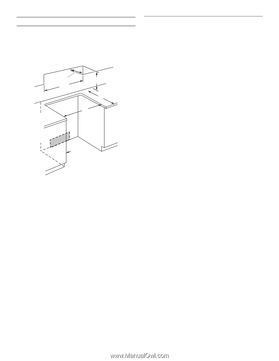
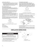
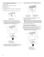
Cabinet Dimensions Cabinet opening dimensions shown are for 25" (64 cm) countertop depth, 24" (61 cm) base cabinet depth and 36" (91.4 cm) countertop height. If installing a range hood or microwave hood combination above the range, follow the range hood or microwave hood combination installation instructions for dimensional clearances above the cooktop surface. A C B D E F G A. 13" (33 cm) upper cabinet depth B. 30" (76.2 cm) min. opening width C. For minimum clearance to the top of the cooktop, see NOTE*. D. 23¹⁄₄" (58.1 cm) opening depth E. 30" (76.2 cm) min. opening width F. Junction box - 5.5" (14 cm) min. from either cabinet, 10" (25.4 cm) max. from floor Outlet must be flush. Nothing located in shaded area can extend more than 2" (5.1 cm) from wall or range will not slide all the way back. G. Cabinet door or hinge should not extend into cutout. NOTE: 24" (61 cm) minimum when bottom of wood or metal cabinet is protected by not less than ¹⁄₄" (0.64 cm) flame retardant millboard covered with not less than No. 28 MSG sheet steel, 0.015" (0.4 mm) stainless steel, 0.024" (0.6 mm) aluminum or 0.020" (0.5 mm) copper. 30" (76.2 cm) minimum clearance between the top of the cooking platform and the bottom of an unprotected wood or metal cabinet. Electrical Requirements If codes permit and a separate ground wire is used, it is recommended that a qualified electrical installer determine that the ground path is adequate and wire gauge is in accordance with local codes. Do not use an extension cord. Be sure that the electrical connection and wire size are adequate and in conformance with the National Electrical Code, ANSI/ NFPA 70-latest edition and all local codes and ordinances. A copy of the above code standards can be obtained from: National Fire Protection Association One Batterymarch Park Quincy, MA 02269 WARNING: Improper connection of the equipment-grounding conductor can result in a risk of electric shock. Check with a qualified electrician or service technician if you are in doubt as to whether the appliance is properly grounded. Do not modify the power supply cord plug. If it will not fit the outlet, have a proper outlet installed by a qualified electrician. This range is manufactured with the neutral terminal connected to the cabinet. Use a 3-wire, UL listed, 40-amp power supply cord (pigtail); or if local codes do not permit ground through the neutral, use a 4-wire power supply cord rated at 250 volts, 40 amps and investigated for use with ranges. Electrical Connection To properly install your range, you must determine the type of electrical connection you will be using and follow the instructions provided for it here. ■ Range must be connected to the proper electrical voltage and frequency as specified on the model/serial number rating plate. (The model/serial number rating plate is located on the oven frame behind the storage drawer panel.) ■ When a 4-wire or 3-wire, single phase 120/240 volt, 60 Hz, AC only electrical supply is available, a 50-amp maximum circuit protection is required (or, if specified on the model/ serial rating plate, when a 4-wire or 3-wire single phase 120/208 volt 60 Hz, AC only electrical supply is available, a 40- or 50-amp maximum circuit protection is required), fused on both sides of the line. ■ A time-delay fuse or circuit breaker is recommended. ■ The range can be connected directly to the fused disconnect (or circuit breaker box) through flexible or nonmetallic sheathed, copper or aluminum cable. See "Electrical Connection." ■ Allow 2 to 3 ft (61.0 cm to 91.4 cm) of slack in the line so that the range can be moved if servicing is ever necessary. ■ A UL listed conduit connector must be provided at each end of the power supply cable (at the range and at the junction box). ■ Wire sizes and connections must conform with the rating of the range (40 amps). ■ The wiring diagram is located on the underside of the storage drawer or below the warming drawer in a clear plastic bag. 3
-
 1
1 -
 2
2 -
 3
3 -
 4
4 -
 5
5 -
 6
6 -
 7
7 -
 8
8 -
 9
9 -
10
-
11
-
12
 |
 |