Whirlpool SKT60S Installation Instructions - Page 4
Assembly Instructions - installation
 |
View all Whirlpool SKT60S manuals
Add to My Manuals
Save this manual to your list of manuals |
Page 4 highlights
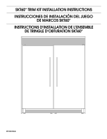
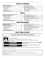
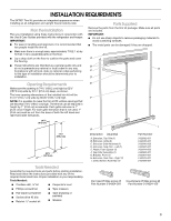
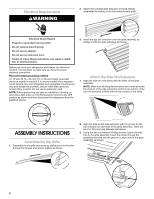
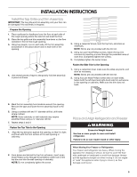
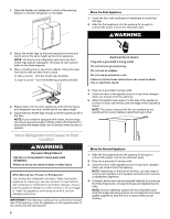
Electrical Requirements WARNING 2. Attach the notched grille extrusion to those already assembled by sliding it into the bottom/lowest grille. Electrical Shock Hazard Plug into a grounded 3 prong outlet. Do not remove ground prong. Do not use an adapter. Do not use an extension cord. Failure to follow these instructions can result in death, fire, or electrical shock. Before you move your refrigerator and freezer into their final location, it is important to make sure you have the proper electrical connection. Recommended grounding method A 115 Volt, 60 Hz., AC only 15- or 20-amp fused, grounded electrical supply is required. It is recommended that a separate circuit serving only your refrigerator and a separate circuit serving only your freezer be provided. Use an outlet that cannot be turned off by a switch. Do not use an extension cord. NOTE: Before performing any type of installation, cleaning, or removing a light bulb, turn the Temperature Control to the OFF position as shown and then disconnect the refrigerator from the electrical source. 3. Install the top trim extrusion onto the grille assembly by sliding it onto the grille extrusion at the top. Attach the Side Trim Extrusions 1. Align the side trim extrusions with the sides of the grille assembly. NOTE: Make sure all the grille extrusions are contained within the channel of the side extrusions and the top surface of the top trim extrusion is flush with the top surface of the sides. ASSEMBLY INSTRUCTIONS Assemble the Top Grille 1. Assemble the six grille extrusions by sliding one into the other through the tongue and groove feature as shown. 2. Align the hole on the side extrusion with the groove on the top extrusion on each side of the grille assembly. There will be a ³⁄₈" (9.5 mm) gap between extrusions. 3. Using the two countersunk Phillips screws, fasten the side trim to the grille assembly. Insert the screw through the predrilled hole and into the groove on each side of the grille assembly as shown. ³⁄₈" (9.5 mm) 4
-
 1
1 -
 2
2 -
 3
3 -
 4
4 -
 5
5 -
 6
6 -
 7
7 -
 8
8 -
 9
9 -
 10
10 -
11
-
12
-
13
-
14
-
15
-
16
-
17
-
18
-
19
-
20
 |
 |