Whirlpool UXT4030ADS Use & Care Guide - Page 6
Mark Hole Locations, Drill Electrical Opening, Prepare Range Hood Vents and, Mounting Tabs
 |
View all Whirlpool UXT4030ADS manuals
Add to My Manuals
Save this manual to your list of manuals |
Page 6 highlights
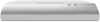
5. Mark Hole Locations 6. Drill Electrical Opening Lift the range hood into place and insert the mounting bracket tabs through the slots in the back of the range hood. A 90˚ Using a 1¹⁄₄" (3 cm) drill bit, drill the hole in the dot marked previously at the electrical strain relief. OPTIONAL: Using a ¹⁄₈" (3 mm) drill bit, drill pilot holes for the dots marked previously at each mounting tab at an approximate 45° angle in an upward direction. 7. Prepare Range Hood Vents and Mounting Tabs x2 C B B Hold the range hood firmly in place with one hand and bend each mounting tab (A) upward approximately 90°. Mark the hole at the power supply knockout (B). OPTIONAL: Mark the hole in each mounting tab. Remove the range hood and set it aside. A ■ Install Strain Relief Install a UL Listed/CSA Approved ¹⁄₂" (13 mm) strain relief (A). ■ Mounting Tabs Start a #8-18 x 4.2 x 16 mm) truss-head screw into the mounting tab (C) on each side of the range hood as shown in the inset. Insert the screws approximately 2 turns into the mounting tab holes. ■ Non-vent (Recirculating) Installations Remove the (2) T10®† Torx® screws and remove the top, front rectangular vent cover (B). †®TORX and T10 are registered trademarks of Acument Intellectual Properties, LLC. 6
-
 1
1 -
 2
2 -
 3
3 -
 4
4 -
 5
5 -
 6
6 -
 7
7 -
 8
8 -
 9
9 -
 10
10 -
 11
11 -
 12
12 -
13
-
14
-
15
-
16
-
17
-
18
-
19
-
20
-
21
-
22
-
23
-
24
 |
 |
