Whirlpool W5CG3024XT Installation Guide - Page 5
Warning
 |
View all Whirlpool W5CG3024XT manuals
Add to My Manuals
Save this manual to your list of manuals |
Page 5 highlights
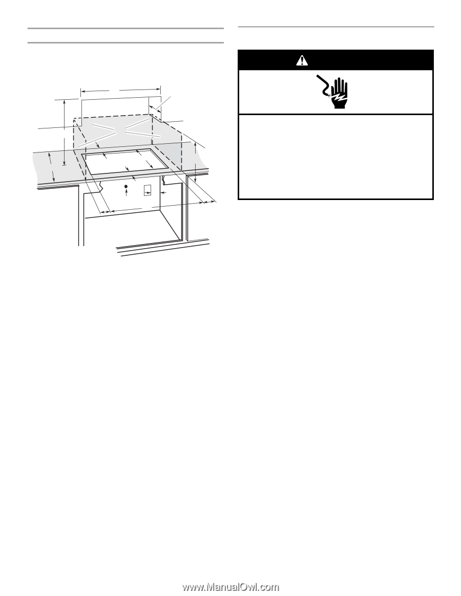
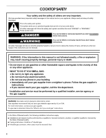
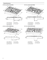
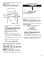
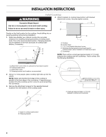
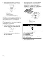
Cabinet Dimensions IMPORTANT: If installing a range hood or microwave hood combination above the cooktop, follow the range hood or microwave hood combination installation instructions for dimensional clearances above the cooktop surface. A D Electrical Requirements WARNING C M B KEF H L J I G J A. 30" (76.2 cm) on 30" models; 36" (91.4 cm) on 36" models B. Combustible area above countertop (shown by dashed box above) C. 30" (76.2 cm) minimum clearance between top of cooktop platform and bottom of uncovered wood or metal cabinet (24" [61 cm] minimum clearance if bottom of wood or metal cabinet is covered by not less than ¹⁄₄" [0.6 cm] flame retardant millboard covered with not less than No. 28 MSG sheet steel, 0.015" [0.04 cm] stainless steel, or 0.024" [0.06 cm] aluminum or 0.020" [0.05 cm] copper) D. 13" (33 cm) recommended upper cabinet depth E. 3¹⁄₈" (7.9 cm) F. 19" (48.3 cm) G. 18" (45.7 cm) minimum clearance from upper cabinet to countertop within minimum horizontal clearances to cooktop H. Grounded outlet - Locate within 24" (61 cm) of right rear corner of cutout (with no undercounter built-in oven installed below cooktop) I. 29" (73.7 cm) on 30" models; 35¼" (89.5 cm) on 36" models J. 8³⁄₈" (21.3 cm) minimum distance to nearest left and right side combustible surface K. 2⁷⁄₈" (7.3 cm) minimum distance to rear combustible surface L. Gas line opening - Wall: Anywhere 5" (12.7 cm) below underside of countertop. Cabinet floor: anywhere within 6" (15.2 cm) of rear wall is recommended (with no undercounter built-in oven installed below cooktop) M. 25" (63.5 cm) minimum countertop depth is required NOTES: After making the countertop cutout, some installations may require notching down the base cabinet side walls to clear the cooktop base. To avoid this modification, use a base cabinet with sidewalls wider than the cutout. If cabinet has a drawer, a 4" (10.2 cm) depth clearance from the countertop to the top of the drawer (or other obstruction) in base cabinet is required. The drawer depth may need to be shortened to avoid interfering with the regulator. IMPORTANT: If an undercounter built-in wall oven is to be installed below this cooktop, the grounded outlet (H) and gas supply piping must be located in an adjacent cabinet. This cooktop and its gas and electrical supply sources must be installed before the undercounter built-in wall oven is installed. Electrical Shock Hazard Plug into a grounded 3 prong outlet. Do not remove ground prong. Do not use an adapter. Do not use an extension cord. Failure to follow these instructions can result in death, fire, or electrical shock. IMPORTANT: The cooktop must be electrically grounded in accordance with local codes and ordinances, or in the absence of local codes, with the National Electrical Code, ANSI/NFPA 70 or Canadian Electrical Code, CSA C22.1. If codes permit and a separate ground wire is used, it is recommended that a qualified electrical installer determine that the ground path is adequate. A copy of the above code standards can be obtained from: National Fire Protection Association One Batterymarch Park Quincy, MA 02269 CSA International 8501 East Pleasant Valley Road Cleveland, Ohio 44131-5575 ■ A 120 volt, 60 Hz, AC only, 15-amp, fused electrical circuit is required. A time-delay fuse or circuit breaker is also recommended. It is recommended that a separate circuit serving only this cooktop be provided. ■ Electronic ignition systems operate within wide voltage limits, but proper grounding and polarity are necessary. Check that the outlet provides 120-volt power and is correctly grounded. ■ The wiring diagrams are provided with this cooktop. See "Wiring Diagrams" on a separate sheet. The wiring diagrams are located on the left underside of the cooktop base. 5
-
 1
1 -
 2
2 -
 3
3 -
 4
4 -
 5
5 -
 6
6 -
 7
7 -
 8
8 -
 9
9 -
 10
10 -
 11
11 -
12
-
13
-
14
-
15
-
16
-
17
-
18
-
19
-
20
-
21
-
22
-
23
-
24
 |
 |