Whirlpool WCG55US0HW Instruction Sheet - Page 8
To Convert Standard Burner, To Convert Dual Tier Ultra and Dual Flame Burners, To Convert Torch
 |
View all Whirlpool WCG55US0HW manuals
Add to My Manuals
Save this manual to your list of manuals |
Page 8 highlights
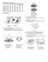
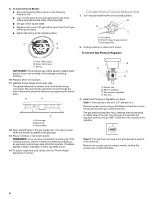
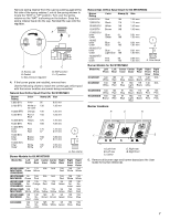
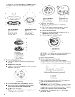
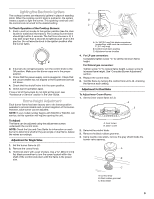
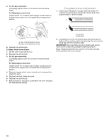
. To remove the burner base for the Dual Flame and Dual Tier A Ultra Torch burners use a Torx® T10 driver to remove the screw. A A B C D Dual Tier Ultra Burner A. Inner burner cap B. Outer burner cap C. Gas tube opening D. Burner base B B D C Standard and Dual Flame A. Burner cap B. Igniter electrode C. Burner base D. Gas tube opening Dual Tier Ultra Burner A. Inner orifice spud B. Outer orifice spud B A Dual Flame Burners A. Inner orifice spud B. Outer orifice spud 8. To Convert Torch Burner ■ Remove the spring that is shown in the following illustration (C). ■ Use 7.0 mm wrench to loosen and remove the inner orifice spud (A) and the outer orifice spud (B). ■ Set gas orifice spuds aside. ■ Replace with correct Natural gas orifice spud. See the Natural gas orifice spud charts. ■ Return the spring to its original location. A C A B B C D E Torch Burner A. Inner burner cap B. Inner burner base C. Outer burner base D. Burner support E. Gas tube opening 6. To Convert Standard Burner: ■ Use 7.0 mm wrench to loosen and remove the orifice spud (A). ■ Set gas orifice spud aside. ■ Replace with correct Natural gas orifice spud. See Natural gas orifice spud charts. A. Inner orifice spud B. Outer orifice spud C. Spring IMPORTANT: Place Natural gas orifice spuds in plastic parts bag for future use and keep with package containing literature. 9. Replace sheet of insulation. 10. Replace burner bases and burner caps. The igniter electrode is ceramic and could break during conversion. Be sure that the electrode comes through the hole in the burner smoothly while you are replacing the burner base. A B A A. Orifice spud 7. To Convert Dual Tier Ultra and Dual Flame Burners: ■ Use 7.0 mm wrench to loosen and remove the inner orifice spud (A) and the outer orifice spud (B). ■ Set gas orifice spuds aside. ■ Replace with correct Natural gas orifice spuds. See the Natural gas orifice spud charts. 8 C A. Burner cap B. Electrode C. Burner base 11. Open shutoff valve in the gas supply line. The valve is open when the handle is parallel to the gas pipe. 12. Plug in cooktop or reconnect power. REMEMBER: Once you have completed converting all of the cooktop burners, test the cooktop for leaks by brushing on an approved noncorrosive leak-detection solution. If bubbles appear, a leak is indicated. Correct any leaks found. 13. To adjust single and dual valves, see the "Flame Height Adjustment" section.
-
 1
1 -
2
-
 3
3 -
 4
4 -
 5
5 -
 6
6 -
 7
7 -
 8
8 -
 9
9 -
 10
10 -
 11
11 -
 12
12 -
 13
13 -
14
-
15
-
16
-
17
-
18
-
19
-
20
 |
 |
