Whirlpool WCG77US0HS Instruction Sheet - Page 4
LP Gas Orifice Spud Chart for Kit W10676661 - gas cooktop
 |
View all Whirlpool WCG77US0HS manuals
Add to My Manuals
Save this manual to your list of manuals |
Page 4 highlights
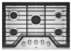
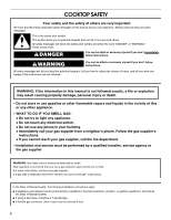
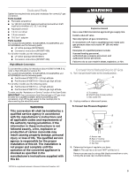
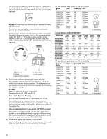
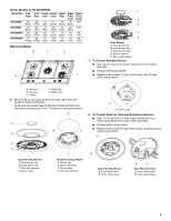
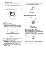
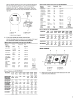
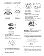
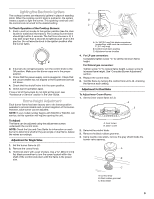
The gas pressure regulator has 2 settings that are stamped on either side of the cap. Turn the cap and reinstall into regulator with the stamp "LP" visible from the outside of the regulator. Style 2: The cap does not have a slot and requires a wrench to be removed. Remove the access cap by using a wrench, turning the access cap counterclockwise. Remove spring retainer from the cap by pushing against the flat side of the spring retainer. Look at the spring retainer to locate the "NAT" or "LP" position. Turn over the spring retainer so the "LP" is showing on the bottom. Snap the spring retainer back into the cap. Reinstall the cap onto the regulator. A B E D C A. Access cap B. Gasket C. Gas pressure regulator D. LP position E. NAT position 4. Test the gas pressure regulator and gas supply line. The regulator must be checked at a minimum 1" (2.5 cm) water column above the set pressure. The inlet pressure to the regulator should be as follows for operation and checking the regulator setting: LP Gas: Minimum pressure 10" (25.4 cm) W.C.P. Supply pressure 14" (35.5 cm) W.C.P. Gas Supply Pressure Testing Line pressure testing above ½ psi gauge (14" WCP) The cooktop and its individual shutoff valve must be disconnected from the gas supply piping system during any pressure testing of that system at test pressures in excess of ½ psi (3.5 kPa). Line pressure testing at ½ psi gauge (14" WCP) or lower The cooktop must be isolated from the gas supply piping system by closing its individual manual shutoff valve during any pressure testing of the gas supply piping system at test pressures equal to or less than ½ psi (3.5 kPa). 5. If the burner grates are installed, remove them. Use the following charts to match the correct gas orifice spud with the burner location and model being converted. LP Gas Orifice Spud Chart for Kit W10676661 Burner Rating Color Stamp (A) Size 5,000 BTU Green 66 0.66 mm 7,000 BTU White 75 0.75 mm 8,000 BTU Orange 79 0.79 mm 11,000 BTU Red 97 0.97 mm 13,000 BTU Yellow 108 1.08 mm 16,000 BTU Pink 115 1.15 mm 12,000 BTU Inner Brown 85 Outer Brown 48 0.85 mm 0.48 mm A A. Size stamp Burner Models for Kit W10676661 Model No. WCG51US0D MGC7430D ICS500DS00 WCG75US0D MGC9530D WCG97US0D KCGS350E ICS655DS00 WCG51US6D MGC7536D WCG97US6D MGC9536D KCGS356E Left Front 66 Green 66 Green 75 White 75 White 75 White Left Rear 108 Yellow Center Inner N/A 115 Pink 79 Orange N/A 85 Brown 75 White 75 White 108 Yellow 85 Brown Center Outer N/A N/A 48 Brown N/A 48 Brown Right Rear 97 Red 97 Red 66 Green 66 Green 66 Green Right Front 75 White 75 White 75 White 97 Red 97 Red LP Gas Orifice Spud Chart for Kit W10676662 Burner Rating Color Stamp (A) Size 5,000 BTU White 66 0.66 mm 6,000 BTU Green 70 0.70 mm 9,100 BTU Black 89 0.89 mm 11,000 BTU Orange 97 0.97 mm 13,000 BTU Inner Blue 45 Outer Brown 97 0.45 mm 0.97 mm 14,000 BTU Inner Blue 45 Outer Yellow 101 0.45 mm 1.01 mm 16,000 BTU Inner Blue 45 Outer Red 105 0.45 mm 1.05 mm 9,000 BTU Inner Pink 40 Outer Pink 80 0.40 mm 0.80 mm A A. Size stamp 4
-
 1
1 -
 2
2 -
 3
3 -
 4
4 -
 5
5 -
 6
6 -
 7
7 -
 8
8 -
 9
9 -
 10
10 -
11
-
12
-
13
-
14
-
15
-
16
-
17
-
18
-
19
-
20
 |
 |