Whirlpool WCI55US0JS Installation Instructions - Page 3
Installation Requirements
 |
View all Whirlpool WCI55US0JS manuals
Add to My Manuals
Save this manual to your list of manuals |
Page 3 highlights
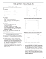
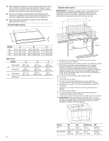
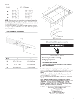
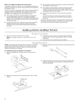
INSTALLATION REQUIREMENTS Tools and Parts Gather the required tools and parts before starting installation. Read and follow the instructions provided with any tools listed here. Tools Needed ■ Tape measure ■ Marker or pencil ■ Flat-blade screwdriver ■ Pliers ■ Phillips head screwdriver ■ 1/4" drill bit ■ Hand or electric drill ■ Jigsaw ■ Level 24" (65 cm) cooktop model/serial rating plate location A Parts Supplied ■ Brackets (2) ■ #6 x 3/4" (1.9 cm) clamping screws (4) ■ #8 x 3/8" (9.5 mm) sheet metal screws (6 screws for 24" [65 cm] models, and 7 screws for 30" [78.2 cm] and 36" [92.2 cm] models) Parts Needed ■ A UL listed or CSA approved strain relief ■ UL listed wire connectors ■ A UL approved junction box or 240 V outlet ■ Cooktop Bracket Adhesive Kit Part Number W11279478 if installing the cooktop into a marble countertop. See the "Assistance or Service" section of the Use and Care Guide for information on ordering. Check local codes. Check existing electrical supply. See "Electrical Requirements". It is recommended that all electrical connections be made by a licensed, qualified electrical installer. Location Requirements Make sure you have everything needed for correct installation. It is the responsibility of the installer to comply with the installation clearances specified in these instructions. IMPORTANT: Observe all governing codes and ordinances. When installing cooktop, use minimum dimensions given. ■ To eliminate the risk of burns or fire by reaching over the heated surface units, cabinet storage space located above the surface units should be avoided. If cabinet storage is to be provided, the risk can be reduced by installing a range hood that projects horizontally a minimum of 5" (12.7 cm) beyond the bottom of the cabinets. ■ It is the installer's responsibility to comply with installation clearances specified on the model/serial rating plate. The model/serial rating plate is located on the underside of the cooktop burner box. A. Model/serial rating plate location 30" (78.2 cm) cooktop model/serial rating plate location A A. Model/serial rating plate location 36" (92.2 cm) cooktop model/serial rating plate location A A. Model/serial rating plate location ■ Check the cooktop base for an approved installation label. Verify approved oven model numbers that can be installed with your cooktop model number. If you do not find this label, your cooktop may not be approved for use over an undercounter built-in oven. Contact your dealer to confirm that your cooktop is approved. ■ Ovens approved for this type of installation will have an approval label located on the top of the oven. If you do not find this label, contact your dealer to confirm that your oven is approved. Refer to oven manufacturer's Installation Instructions for approval for built-in undercounter use and proper cutout dimensions. 3
-
 1
1 -
 2
2 -
 3
3 -
 4
4 -
 5
5 -
 6
6 -
 7
7 -
 8
8 -
 9
9 -
10
-
11
-
12
-
13
-
14
-
15
-
16
-
17
-
18
-
19
-
20
-
21
-
22
-
23
-
24
-
25
-
26
-
27
-
28
 |
 |
