Whirlpool WED70HEBW Ventilation Specification - Page 6
AF Code - dryer
 |
View all Whirlpool WED70HEBW manuals
Add to My Manuals
Save this manual to your list of manuals |
Page 6 highlights
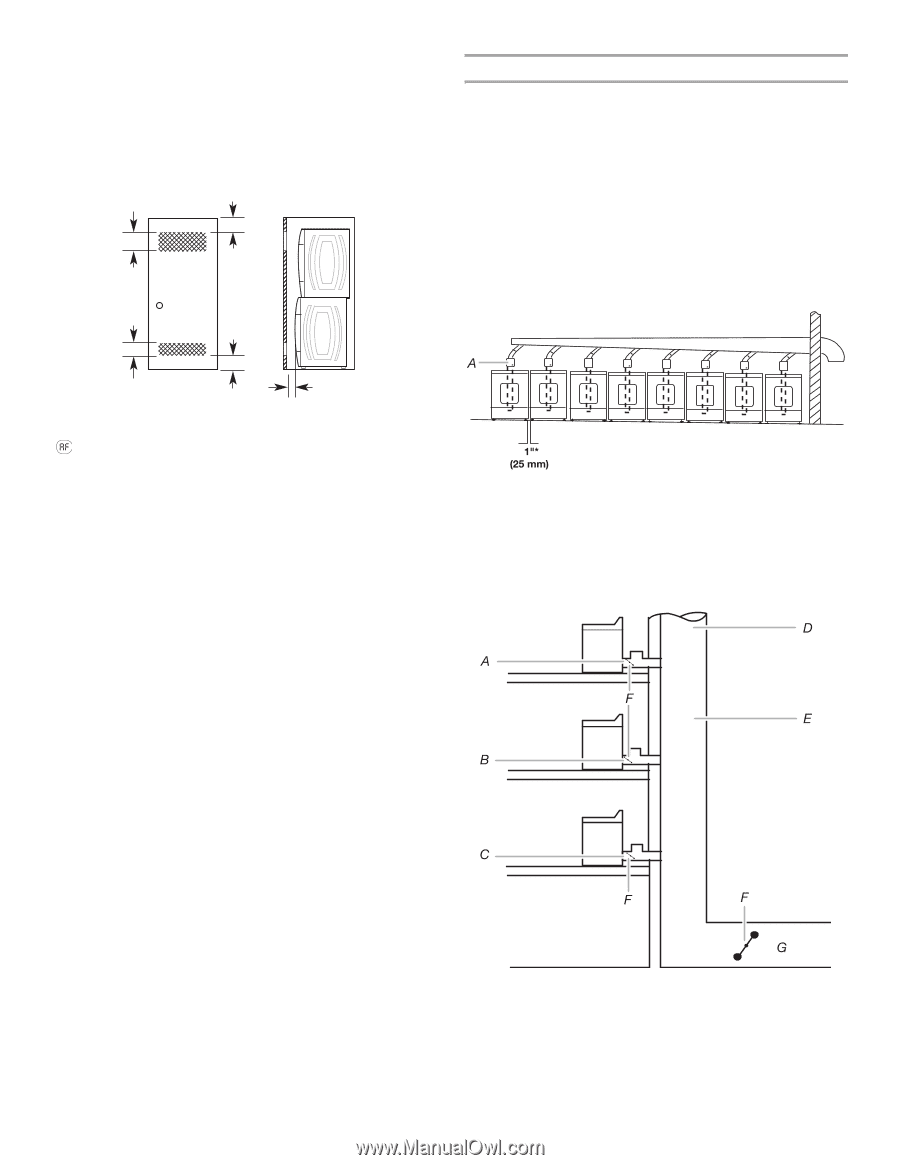
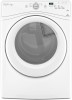
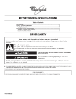
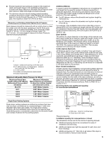
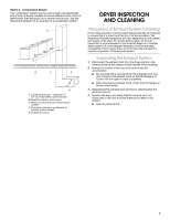
■ For closet installation, with a door, minimum ventilation openings near the top and bottom of the door are required. Louvered doors with equivalent ventilation openings are acceptable. ■ Companion appliance spacing should also be considered. Recommended room venting and installation spacing for recessed or closet installation, with stacked washer and dryer 48 in.2 * (310 cm2) 3"* (76 mm) Multiple Dryer Venting Systems Multiple dryer venting systems must be designed specifically for each application. NOTE: It is recommended that an architectural or HVAC engineering firm be consulted for designing the dryer venting system. Connecting a number of dryers to a single vent system is common in coin-laundry stores and in many apartment buildings. Listed here are some requirements for examples of three different multiple dryer venting systems. Option 1 - Horizontal System The most common is the horizontal system, in which banks of dryers are all located in one room and vented through a common duct. See the following illustration for an example of a generic horizontal system. 24 in.2 * (155 cm2) *Recommended spacing. 3"* (76 mm) 1"* (25 mm) "AF" Code Certain electronic dryer models have airflow detection capabilities. (See specific model product literature for details). If the airflow in the dryer is extremely low, an "AF" code will be displayed on the control panel. For single dryer venting systems, this code means that you may have a blocked or partially blocked vent or that your overall vent system length is too long. To resolve this issue: ■ Check to see if the vent run from the dryer to the wall is crushed. Refer to the "Venting Requirements" section of the Use and Care Guide for more information. ■ Confirm that the vent run from the dryer to the wall is free of lint and debris. ■ Confirm that the exterior vent exhaust hood is free of lint and debris. ■ Confirm that your vent system falls within the recommended run length and number of elbows for the type of vent you are using. Refer to the "Plan Vent System" section of the Use and Care Guide for details. ■ Select a Timed Dry heated cycle, and restart the dryer. ■ If the message persists, have your entire home venting run cleaned. For multi-dryer venting systems, the "AF" code means that your vent may be blocked or partially blocked or that the venting system is creating back pressure in excess of the maximum allowed. In this case, the engineering firm that designed the system should be consulted. A. 4" (102 mm) diameter rigid metal back draft damper *Minimum spacing required between dryers Option 2 - Vertical System The vertical system is used in some apartment buildings that have a washer and dryer on each floor. Each dryer is exhausted into the same central vertical duct. See the following illustration for an example of a generic vertical system. A. Maximum back pressure measurement location B. Weighted dampers C. Individual dryer exhaust - on each floor D. 0.1" (2.5 mm) water column maximum vacuum E. Main duct F. Barometric damper (use depends on exhaust system design) G. Source of outside air 6
-
 1
1 -
 2
2 -
 3
3 -
 4
4 -
 5
5 -
 6
6 -
 7
7 -
 8
8
 |
 |