Whirlpool WED7500VW Ventilation Specification - Page 6
Option 1 - Horizontal System, Option 2 - Vertical System, Option 3 - Com, ination System - washer
 |
UPC - 883049138251
View all Whirlpool WED7500VW manuals
Add to My Manuals
Save this manual to your list of manuals |
Page 6 highlights
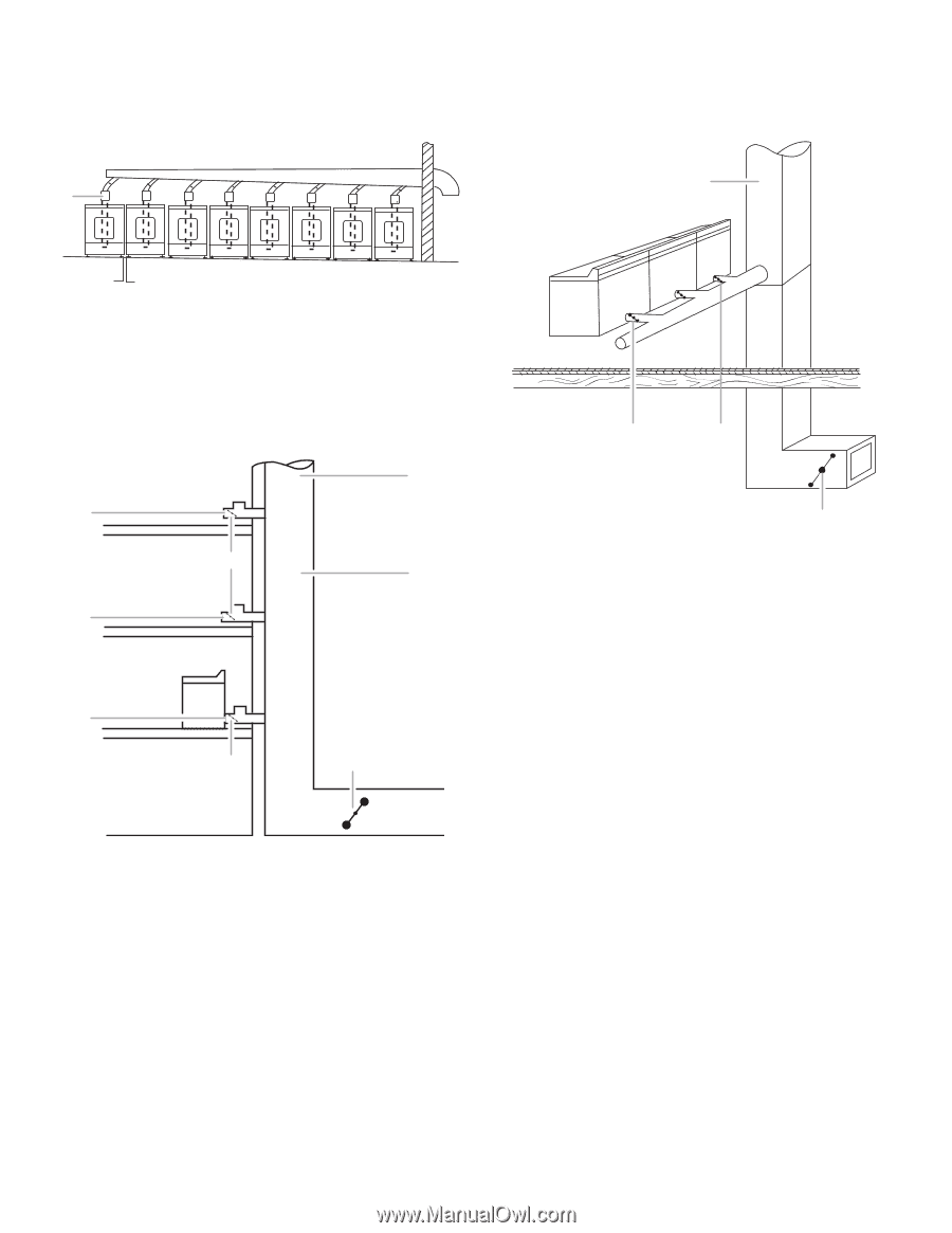
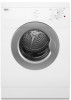
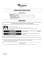
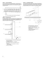
Option 1 - Horizontal System The most common is the horizontal system, in which banks of dryers are all located in one room and vented through a common duct. See the following illustration for an example of a generic horizontal system. Option 3 - Combination System The combination system may be used in high-rise apartments, with a bank of dryers installed at several different levels. Each of these banks then exhausts into a central vertical vent. See the following illustration for an example of a combination system. A A 1"* (25 mm) A. 4" (102 mm) diameter rigid metal back draft damper *Minimum spacing required between dryers Option 2 - Vertical System The vertical system is used in some apartment buildings that have a washer and dryer on each floor. Each dryer is exhausted into the same central vertical duct. See the following illustration for an example of a generic vertical system. D A F E B C F F G A. 0.6" (15 mm) water column maximum back pressure B. Weighted dampers C. Individual dryer exhaust - on each floor D. 0.1" (2.5 mm) water column maximum vacuum E. Main duct F. Barometric damper (use depends on exhaust system design) G. Source of outside air E B C D A. Central vertical duct - maximum of 0.1" (2.5 mm) water column vacuum B. Weighted damper (each dryer) C. Maximum of 0.6" (15 mm) water column back pressure D. Barometric damper (use depends on exhaust system design) E. Outside air source 6
-
 1
1 -
 2
2 -
 3
3 -
 4
4 -
 5
5 -
 6
6 -
 7
7 -
 8
8
 |
 |