Whirlpool WEG515S0F Installation Instructions
Whirlpool WEG515S0F Manual
 |
View all Whirlpool WEG515S0F manuals
Add to My Manuals
Save this manual to your list of manuals |
Whirlpool WEG515S0F manual content summary:
- Whirlpool WEG515S0F | Installation Instructions - Page 1
D'INSTALLATION 23 Outils et pièces 23 Exigences d'emplacement 23 Spécifications électriques 25 Spécifications de l'alimentation en gaz 25 INSTRUCTIONS D'INSTALLATION 27 Déballage de la cuisinière 27 Installation de la bride antibasculement 27 Réglage des pieds de nivellement 28 Réglage - Whirlpool WEG515S0F | Installation Instructions - Page 2
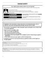
very important. We have provided many important safety messages in this manual and on your appliance. Always read and obey all safety instructions. • If you cannot reach your gas supplier, call the fire department. - Installation and service must be performed by a qualified installer, service - Whirlpool WEG515S0F | Installation Instructions - Page 3
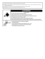
be killed. Install anti-tip bracket to floor or wall per installation instructions. Slide range back so rear range foot is engaged in the slot range without anti-tip bracket installed and engaged. Failure to follow these instructions can result in death or serious burns to children and adults. Anti - Whirlpool WEG515S0F | Installation Instructions - Page 4
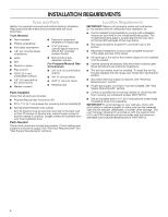
INSTALLATION REQUIREMENTS Tools and Parts Gather the required tools and parts before starting installation. Read and follow the instructions provided with any tools listed here. Tools Needed ■■ Tape measure ■■ Phillips screwdriver ■■ Flat-blade screwdriver ■■ 1/8" (3.2 mm) flat-blade screwdriver - Whirlpool WEG515S0F | Installation Instructions - Page 5
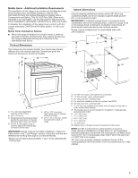
conforms to the standards listed above. Product Dimensions This manual covers several models. Your model may appear different from the to back of range IMPORTANT: Range must be level after installation. Follow the instructions in the "Level Range" section. Using the cooktop as a reference for - Whirlpool WEG515S0F | Installation Instructions - Page 6
an adapter. Do not use an extension cord. Failure to follow these instructions can result in death, fire, or electrical shock. IMPORTANT: The range supplier. Propane Gas Conversion: Conversion must be done by a qualified service technician. No attempt shall be made to convert the appliance from the - Whirlpool WEG515S0F | Installation Instructions - Page 7
inlet to the appliance pressure regulator. ■■ Do not kink or damage the flexible metal tubing when moving the range. ■■ Must include a shut-off valve: Install a manual gas line shut-off valve in an easily accessible location. Do not block access to shut-off valve. The valve is for turning on or - Whirlpool WEG515S0F | Installation Instructions - Page 8
the other 2 corners. Place them lengthwise on the floor behind the range to support the range when it is laid on its back. 4. Using 2 or more people and be killed. Install anti-tip bracket to floor or wall per installation instructions. Slide range back so rear range foot is engaged in the slot of - Whirlpool WEG515S0F | Installation Instructions - Page 9
. This may be done with the range on its back or with the range supported on 2 legs after the range has been placed back to a standing position. top of the cooktop should be higher than the counter. See the Installation Instructions included with the Trim Kit for the correct height. Level Range 1. - Whirlpool WEG515S0F | Installation Instructions - Page 10
licensed heating personnel, authorized gas company personnel, and authorized service personnel. Failure to do so can result in death, explosion Gas pressure regulator shut-off valve shown in the "on" position 2. Open the manual shut-off valve in the gas supply line. The valve is open when the handle - Whirlpool WEG515S0F | Installation Instructions - Page 11
use an adapter. Do not use an extension cord. Failure to follow these instructions can result in death, fire, or electrical shock. 6. Plug into a your dealer or authorized service company for assistance. Please reference the "Warranty" section of the User Guide to contact service. If the cooktop low - Whirlpool WEG515S0F | Installation Instructions - Page 12
"Range Care" section of the User Guide. 7. Read the User Guide. 8. Turn on surface burners and oven. See the User Guide for specific instructions on range operation. NOTE: Odors and . If You Need Assistance or Service: Please reference the "Warranty" section of the User Guide to contact service. 12 - Whirlpool WEG515S0F | Installation Instructions - Page 13
licensed heating personnel, authorized gas company personnel, and authorized service personnel. Failure to do so can result in death, instructions can result in death or serious burns to children and adults. 1. Turn the manual shut-off valve to the closed position. B A C A. Gas supply line B. Manual - Whirlpool WEG515S0F | Installation Instructions - Page 14
3. Remove plastic cover from gas pressure regulator cap. 4. Turn gas pressure regulator cap counterclockwise with a 5/8" (1.6 cm) combination wrench to remove. NOTE: Do not remove the spring beneath the cap. Side view before A 4. Remove the orifice spuds shipped in the literature package in the - Whirlpool WEG515S0F | Installation Instructions - Page 15
5. Slide the front of the bake burner to the side to remove tab from front of oven. Lift the back of the bake burner off the oven orifice and set the bake burner aside. Do not disconnect the wire. A B To Convert Oven Broil Burner (Natural Gas to Propane Gas) (on some models) 1. Remove the 1 screw - Whirlpool WEG515S0F | Installation Instructions - Page 16
as distinct as the inner cone. Propane gas flames have a slightly yellow tip. 4. Refer to "Complete Installation" in the "Installation Instructions" section of this manual to complete this procedure. IMPORTANT: Make sure to save the orifices that have just been replaced in the conversion. Natural - Whirlpool WEG515S0F | Installation Instructions - Page 17
4. Turn gas pressure regulator cap counterclockwise with a 5/8" (1.6 cm) combination wrench to remove. NOTE: Do not remove the spring beneath the cap. Side view before A 4. Gas orifice spuds are stamped with a number on the side. Replace the Propane gas orifice spud with the correct Natural gas - Whirlpool WEG515S0F | Installation Instructions - Page 18
4. Remove 2 screws from the bake burner. 5. Slide the front of the bake burner to the side to remove tab from front of oven. Lift the back of the bake burner off the oven orifice, and set the bake burner aside. Do not disconnect the wire. A B A. Bake burner B. Screws A 10. Position the front of the - Whirlpool WEG515S0F | Installation Instructions - Page 19
not have yellow tips. 4. Refer to "Complete Installation" in the "Installation Instructions" section of this manual to complete this procedure. IMPORTANT: Make sure to save the orifices that have Operation of Oven Bake Burner Refer to the User Guide for proper operation of the oven controls. 19 - Whirlpool WEG515S0F | Installation Instructions - Page 20
Adjust Oven Bake Burner Flame (If Needed) 1. Remove the storage drawer(see the "Remove/Replace Drawer" section). 2. Locate gas pressure regulator at rear of the drawer compartment. A 4. If the oven bake flame needs to be adjusted, locate the air shutter near the center rear of the drawer cavity - Whirlpool WEG515S0F | Installation Instructions - Page 21
entretien doivent être effectués par un installateur qualifié, une agence de service ou le fournisseur de gaz. AVERTISSEMENT : L'odorat ne permet pas gaz local. En cas de détection d'une fuite de gaz, exécuter les instructions "Que faire dans le cas d'une odeur de gaz". IMPORTANT : Ne pas installer - Whirlpool WEG515S0F | Installation Instructions - Page 22
Fixer la bride antibasculement au plancher ou au mur, conformément aux instructions d'installation. Faire glisser de nouveau la cuisinière de façon à antibasculement n'est pas installée et engagée. Le non-respect de ces instructions peut causer un décès ou des brûlures graves aux enfants et aux - Whirlpool WEG515S0F | Installation Instructions - Page 23
D'INSTALLATION Outils et pièces Rassembler les outils et pièces nécessaires avant d'entreprendre l'installation. Lire et observer les instructions fournies avec chacun des outils de la liste ci-dessous. Outils nécessaires ■■ Ruban à mesurer ■■ Tournevis cruciforme ■■ Tournevis à lame plate - Whirlpool WEG515S0F | Installation Instructions - Page 24
de profondeur maximale entre la poignée et l'arrière de la cuisinière IMPORTANT : La cuisinière doit être d'aplomb après l'installation. Suivre les instructions de la section "Réglage de l'aplomb de la cuisinière". Il n'est pas recommandé d'utiliser la table de cuisson comme référence pour établir - Whirlpool WEG515S0F | Installation Instructions - Page 25
la broche de liaison à la terre. Ne pas utiliser un adaptateur. Ne pas utiliser un câble de rallonge. Le non-respect de ces instructions peut causer un décès, un incendie ou un choc électrique. IMPORTANT : La cuisinière doit être électriquement reliée à la terre conformément aux prescriptions - Whirlpool WEG515S0F | Installation Instructions - Page 26
Canalisation d'alimentation en gaz ■■ Installer une canalisation d'alimentation en gaz rigide de 3/4" (1,9 cm) jusqu'à l'emplacement d'installation de la cuisinière. L'emploi d'une canalisation de plus petit diamètre ou plus longue peut susciter une déficience du débit d'alimentation. Pour l' - Whirlpool WEG515S0F | Installation Instructions - Page 27
plancher dans le sens de la longueur derrière la cuisinière, à titre de support de la cuisinière lorsque celle-ci est placée sur sa partie postérieure. Fixer la bride antibasculement au plancher ou au mur, conformément aux instructions d'installation. Faire glisser de nouveau la cuisinière de façon - Whirlpool WEG515S0F | Installation Instructions - Page 28
Fixer la bride antibasculement au plancher ou au mur, conformément aux instructions d'installation. Faire glisser de nouveau la cuisinière de façon bride antibasculement n'est pas installée et engagée. Le non-respect de ces instructions peut causer un décès ou des brûlures graves aux enfants et aux - Whirlpool WEG515S0F | Installation Instructions - Page 29
le personnel autorisé de chauffage, le personnel autorisé d'une compagnie de gaz, et le personnel d'entretien autorisé. Le non-respect de ces instructions peut causer un décès, une explosion ou un incendie. Cette cuisinière a été configurée à l'usine pour l'alimentation au gaz naturel. Pour utiliser - Whirlpool WEG515S0F | Installation Instructions - Page 30
arrivée de gaz de la base du brûleur avec le support d'injecteur à orifice sur la table de cuisson et l'électrode ble de rallonge. Le non-respect de ces instructions peut causer un décès, un incendie ou un choc la section "Garantie" du guide d'utilisation pour contacter le service de maintenance. Si la - Whirlpool WEG515S0F | Installation Instructions - Page 31
panneur agréé. Se reporter à la section "Garantie" du guide d'utilisation pour contacter le service de maintenance. Si la flamme du brûleur de cuisson , s'assurer que le four est éteint et froid. Ensuite, suivre les instructions ci-dessous. La porte du four est lourde. Démontage : 1. Ouvrir la - Whirlpool WEG515S0F | Installation Instructions - Page 32
Pour des instructions spécifiques concernant l'utilisation de la cuisinière, consulter le Guide d'utilisation et d'entretien ou les instructions d'utilisation. ou une visite de service : Se reporter à la section "Garantie" du Guide d'utilisation pour contacter le service de maintenance. REMARQUE - Whirlpool WEG515S0F | Installation Instructions - Page 33
Fixer la bride antibasculement au plancher ou au mur, conformément aux instructions d'installation. Faire glisser de nouveau la cuisinière de façon bride antibasculement n'est pas installée et engagée. Le non-respect de ces instructions peut causer un décès ou des brûlures graves aux enfants et aux - Whirlpool WEG515S0F | Installation Instructions - Page 34
propane Consulter le tableau qui suit permet de sélectionner la capacité correcte d'injecteur à orifice pour propane, et consulter la carte du support d'injecteur à orifice pour connaître l'emplacement correct. Injecteurs à orifice pour propane - brûleurs de surface Capacité/type de brûleur Taille - Whirlpool WEG515S0F | Installation Instructions - Page 35
4. Ôter 2 vis du brûleur de cuisson au four. 5. Faire glisser l'avant du brûleur de cuisson au four sur le côté pour retirer l'onglet de l'avant du four. Soulever l'arrière du brûleur de cuisson au four de l'orifice du four, et mettre le brûleur de cuisson au four de côté. Ne pas déconnecter le fil. - Whirlpool WEG515S0F | Installation Instructions - Page 36
Fixer la bride antibasculement au plancher ou au mur, conformément aux instructions d'installation. Faire glisser de nouveau la cuisinière de façon bride antibasculement n'est pas installée et engagée. Le non-respect de ces instructions peut causer un décès ou des brûlures graves aux enfants et aux - Whirlpool WEG515S0F | Installation Instructions - Page 37
mettre de côté sur une surface couverte. A B A. Vis B. Partie inférieure du four 4. Ôter 2 vis du brûleur de cuisson au four. A. Électrode d'allumage B. Injecteur à orifice C. Support de l'injecteur à orifice D. Vis 37 - Whirlpool WEG515S0F | Installation Instructions - Page 38
5. Faire glisser l'avant du brûleur de cuisson au four sur le côté pour retirer l'onglet de l'avant du four. Soulever l'arrière du brûleur de cuisson au four de l'orifice du four, et mettre le brûleur de cuisson au four de côté. Ne pas déconnecter le fil. A B A. Brûleur de cuisson au four B. Vis 9. - Whirlpool WEG515S0F | Installation Instructions - Page 39
flammes d'un brûleur alimenté au gaz naturel ne comportent pas de pointe jaune. 4. Voir le paragraphe "Achever l'installation" de la section "Instructions d'installation" de ce manuel pour achever cette procédure. IMPORTANT : S'assurer de bien conserver les injecteurs à orifice qui ont été remplac - Whirlpool WEG515S0F | Installation Instructions - Page 40
Contrôle du fonctionnement du brûleur de cuisson au four Consulter le Guide d'utilisation pour le bon fonctionnement des commandes du four. Réglage de la taille des flammes sur le brûleur du four (le cas échéant) 1.
-
 1
1 -
 2
2 -
 3
3 -
 4
4 -
 5
5 -
 6
6 -
 7
7 -
8
-
9
-
10
-
11
-
12
-
13
-
14
-
15
-
16
-
17
-
18
-
19
-
20
-
21
-
22
-
23
-
24
-
25
-
26
-
27
-
28
-
29
-
30
-
31
-
32
-
33
-
34
-
35
-
36
-
37
-
38
-
39
-
40
 |
 |

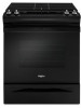
INSTALLATION INSTRUCTIONS
30" (76.2 CM) FRONT CONTROL GAS
RANGES
INSTRUCTIONS D’INSTALLATION DES
CUISINIÈRES À COMMANDES FRONTALES
DE 30" (76,2 CM)
IMPORTANT:
Installer:
Leave installation instructions with the homeowner.
Homeowner:
Keep installation instructions for future reference.
IMPORTANT :
Installateur :
Remettre les instructions d’installation au propriétaire.
Propriétaire :
Conserver les instructions d’installation pour référence ultérieure.
W11124015C
Table of Contents
Table des matières
RANGE SAFETY
.............................................................................
2
INSTALLATION REQUIREMENTS
.................................................
4
Tools and Parts
.............................................................................
4
Location Requirements
................................................................
4
Electrical Requirements
...............................................................
6
Gas Supply Requirements
...........................................................
6
INSTALLATION INSTRUCTIONS
...................................................
8
Unpack Range
..............................................................................
8
Install Anti-Tip Bracket
.................................................................
8
Adjust Leveling Legs
....................................................................
9
Level Range
..................................................................................
9
Make Gas Connection
...............................................................
10
Verify Anti-Tip Bracket Is Installed and Engaged
......................
11
Electronic Ignition System
.........................................................
11
Remove/Replace Drawer
...........................................................
12
Oven Door
..................................................................................
12
Complete Installation
.................................................................
12
GAS CONVERSIONS
....................................................................
13
Propane Gas Conversion
...........................................................
13
Natural Gas Conversion
.............................................................
16
Adjust Flame Height
...................................................................
19
SÉCURITÉ DE LA CUISINIÈRE
...................................................
21
EXIGENCES D’INSTALLATION
...................................................
23
Outils et pièces
...........................................................................
23
Exigences d’emplacement
.........................................................
23
Spécifications électriques
..........................................................
25
Spécifications de l’alimentation en gaz
.....................................
25
INSTRUCTIONS D’INSTALLATION
.............................................
27
Déballage de la cuisinière
..........................................................
27
Installation de la bride antibasculement
....................................
27
Réglage des pieds de nivellement
.............................................
28
Réglage de l’aplomb de la cuisinière
.........................................
29
Raccordement au gaz
................................................................
29
Vérifier que la bride antibasculement
est bien installée et engagée
.....................................................
30
Système d’allumage électronique
..............................................
30
Dépose et réinstallation du tiroir
................................................
31
Porte du four
..............................................................................
31
Achever l’installation
..................................................................
32
CONVERSIONS POUR CHANGEMENT DE GAZ
......................
33
Conversion pour l’alimentation au propane
..............................
33
Conversion pour l’alimentation au gaz naturel
..........................
36
Réglage de la taille des flammes
...............................................
39