Whirlpool WEG515S0FS Installation Guide - Page 10
Make Gas Connection - gas range
 |
View all Whirlpool WEG515S0FS manuals
Add to My Manuals
Save this manual to your list of manuals |
Page 10 highlights
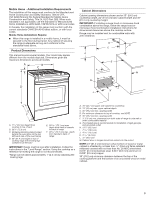
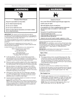
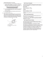
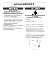
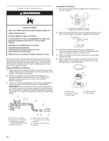
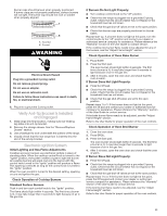
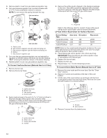
Make Gas Connection WARNING Complete Connection 1. Check that the gas pressure regulator shut-off valve is in the "on" position. Explosion Hazard Use a new CSA International approved gas supply line. Install a shut-off valve. Securely tighten all gas connections. If connected to LP, have a qualified person make sure gas pressure does not exceed 14" (36 cm) water column. Examples of a qualified person include: licensed heating personnel, authorized gas company personnel, and authorized service personnel. Failure to do so can result in death, explosion, or fire. This range is factory-set for use with Natural gas. To use this range with LP gas, see the "Gas Conversions" section before connecting this range to the gas supply. Gas conversions from Natural gas to LP gas or from LP gas to Natural gas must be done by a qualified installer. Typical Flexible Connection 1. Apply pipe-joint compound made for use with LP gas to the smaller thread ends of the flexible connector adapters. See B and G in the following illustration. 2. Attach one adapter to the gas pressure regulator and the other adapter to the gas shut-off valve. Tighten both adapters, being certain not to move or turn the gas pressure regulator. 3. Use a 15/16" (2.4 cm) combination wrench and an adjustable wrench to attach the flexible connector to the adapters. IMPORTANT: All connections must be wrench-tightened. Do not make connections to the gas regulator too tight. Making the connections too tight may crack the regulator and cause a gas leak. Do not allow the regulator to turn when tightening fittings. A BC D E A A. Gas pressure regulator shut-off valve shown in the "on" position 2. Open the manual shut-off valve in the gas supply line. The valve is open when the handle is parallel to the gas pipe. A B A. Closed valve B. Open valve 3. Test all connections by brushing on an approved noncorrosive leak-detection solution. If bubbles appear, a leak is indicated. Correct any leak found. 4. Remove cooktop burner caps and bases from package containing parts. 5. Align the gas tube opening in the burner base with the orifice holder on the cooktop and the igniter electrode with the notch in the burner base. A B C E D A. Burner cap B. Gas tube opening C. Burner base D. Igniter electrode E. Orifice holder A. Gas pressure regulator B. Use pipe-joint compound. C. Adapter (must have ½" [1.3 cm] male pipe thread) D. Flexible connector HG F E. Manual gas shut-off valve F. ½" (1.3 cm) or ¾" (1.9 cm) gas pipe G. Use pipe-joint compound. H. Adapter 10
-
 1
1 -
2
-
3
-
4
-
 5
5 -
 6
6 -
 7
7 -
 8
8 -
 9
9 -
 10
10 -
 11
11 -
 12
12 -
 13
13 -
 14
14 -
 15
15 -
16
-
17
-
18
-
19
-
20
-
21
-
22
-
23
-
24
-
25
-
26
-
27
-
28
-
29
-
30
-
31
-
32
-
33
-
34
-
35
-
36
-
37
-
38
-
39
-
40
 |
 |
