Whirlpool WFE320M0AW Installation Guide - Page 11
wire Connection: Direct Wire, Bare Wire Torque Specifications
 |
View all Whirlpool WFE320M0AW manuals
Add to My Manuals
Save this manual to your list of manuals |
Page 11 highlights
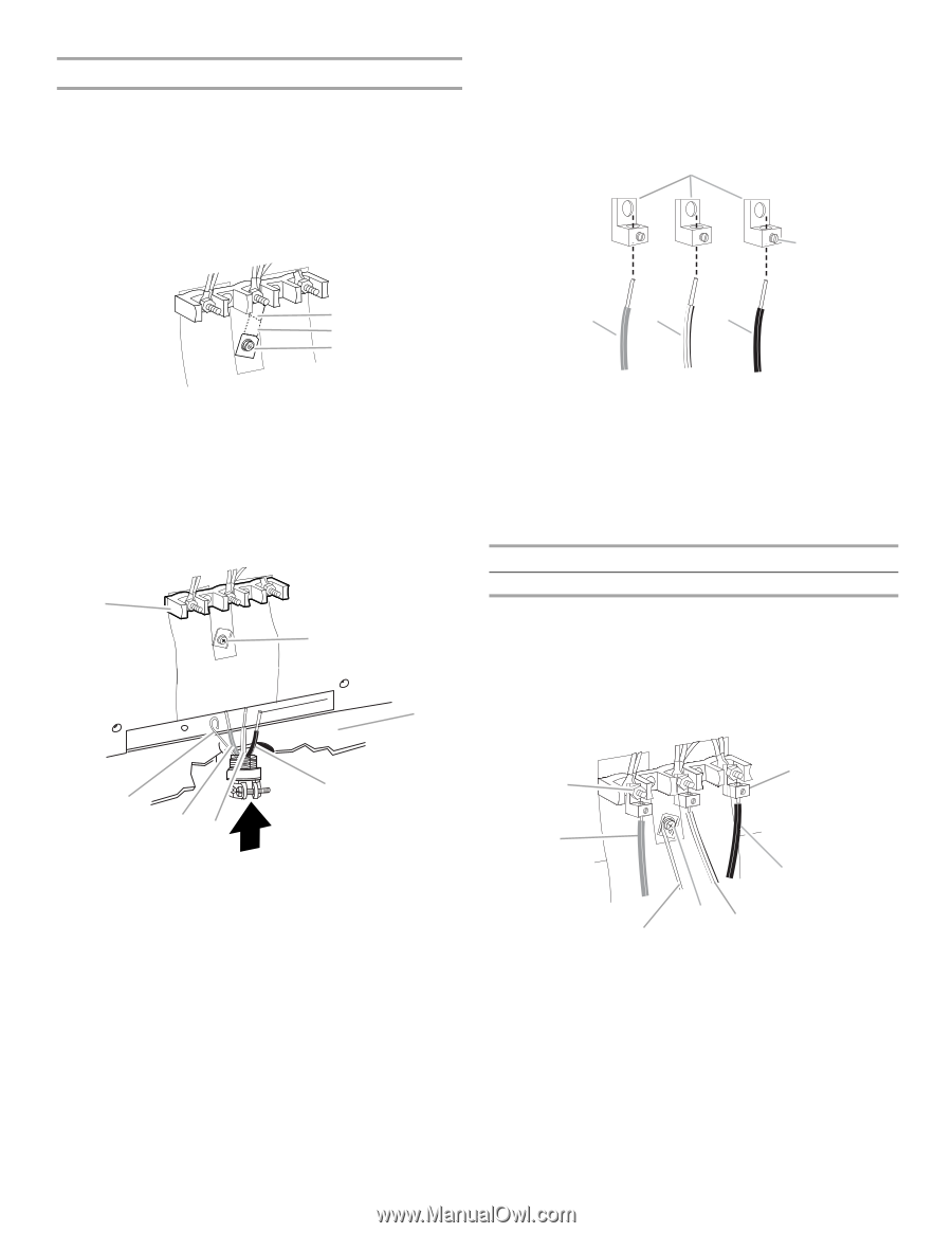
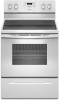
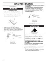
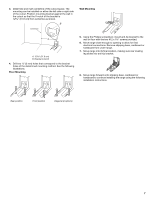
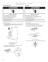
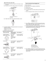
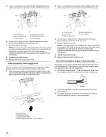
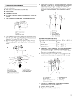
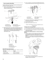
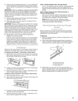
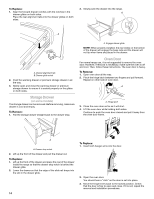
4-wire Connection: Direct Wire Use this method for: ■ New branch-circuit installations (1996 NEC) ■ Mobile homes ■ Recreational vehicles ■ In an area where local codes prohibit grounding through the neutral 1. Part of metal ground strap must be cut out and removed. 4. Attach terminal lugs to line 1 (black), neutral (white), and line 2 (red) wires. Loosen (do not remove) the setscrew on the front of the terminal lug and insert exposed wire end through bottom of terminal lugs. Securely tighten setscrew to torque as shown in the following Bare Wire Torque Specifications chart. A B A B C A. Metal ground strap B. Discard C. Ground-link screw 2. Use a Phillips screwdriver to remove the ground-link screw from the back of the range. Save the ground-link screw and the end of the ground link under the screw. 3. Pull the wires through the strain relief on bottom of range. Allow enough slack to easily attach wiring to the terminal block. A B C C D E A. Terminal lug B. Setscrew C. Line 2 (red) wire D. Neutral (white) wire E. Line 1 (black) wire Bare Wire Torque Specifications Attaching terminal lugs to the terminal block - 20 lbs-in. (2.3 N-m) Wire Awg Torque 8 gauge copper 6 gauge aluminum 25 lbs-in. (2.8 N-m) 35 lbs-in. (4.0 N-m) 5. Use a hex or Phillips screwdriver to connect the bare (green) ground wire to the range with the ground-link screw and ground-link section. The ground wire must be attached first and must not contact any other terminal. 6. Use ³⁄₈" nut driver to connect the neutral (white) wire to the center terminal block post with one of the 10-32 hex nuts. G D EF A. Terminal block B. Ground-link screw C. Cord/conduit plate D. Bare (green) ground wire E. Line 2 (red) wire F. Neutral (white) wire G. Line 1 (black) wire G A B F DE C A. 10-32 hex nut B. Line 2 (red) C. Bare (green) ground wire D. Ground-link screw E. Neutral (white) wire F. Line 1 (black) G. Terminal lug 7. Connect line 2 (red) and line 1 (black) wires to the outer terminal block posts with 10-32 hex nuts. 8. Securely tighten hex nuts. 9. Replace terminal block access cover. 11
-
 1
1 -
2
-
3
-
4
-
5
-
 6
6 -
 7
7 -
 8
8 -
 9
9 -
 10
10 -
 11
11 -
 12
12 -
 13
13 -
 14
14 -
 15
15 -
 16
16
 |
 |