Whirlpool WFG525S0HV Installation Instructions - Page 9
Make Gas Connection
 |
View all Whirlpool WFG525S0HV manuals
Add to My Manuals
Save this manual to your list of manuals |
Page 9 highlights
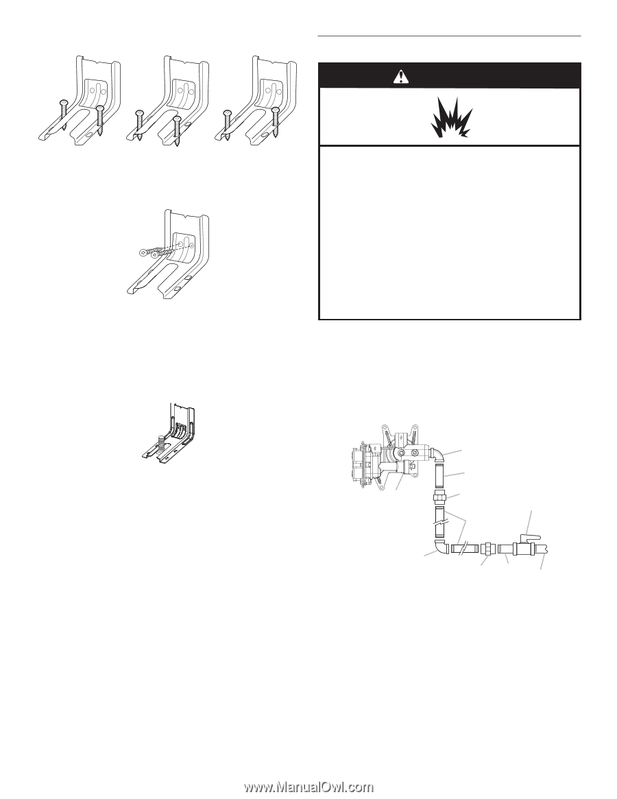
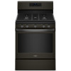
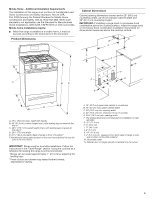
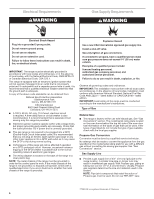
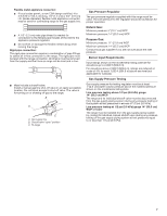
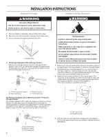
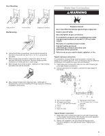
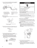
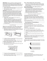
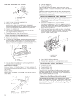
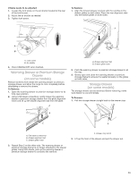
Floor Mounting Make Gas Connection WARNING Rear position Wall Mounting Front position Diagonal (2 options) 5. Using the Phillips screwdriver, mount anti-tip bracket to the wall or floor with the two #12 x 15⁄8" (4.1 cm) screws provided. 6. Move range close enough to opening to allow for final gas and electrical connections. Remove shipping base, cardboard or hardboard from under range. 7. Move range into its final location, making sure rear leveling leg slides into anti-tip bracket. Explosion Hazard Use a new CSA International approved gas supply line. Install a shut-off valve. Securely tighten all gas connections. If connected to propane, have a qualified person make sure gas pressure does not exceed 14" (36 cm) water column. Examples of a qualified person include: licensed heating personnel, authorized gas company personnel, and authorized service personnel. Failure to do so can result in death, explosion, or fire. Typical rigid pipe connection A combination of pipe fittings must be used to connect the range to the existing gas line. Your connections may be different, according to the supply line type, size and location. 1. Apply pipe-joint compound made for use with Propane gas to all pipe thread connections. 2. Using a pipe wrench to tighten, connect the gas supply to the range. 8. Move range forward onto shipping base, cardboard or hardboard to continue installing the range using the following installation instructions. B C A D F E J I HG A. Gas pressure regulator B. 90° elbow (must have 1/3" [1.2 cm] male pipe thread) C. Nipple D. Union E. Black iron pipe F. Manual gas shutoff valve G. 1/2" (1.3 cm) or 3/4" (1.9 cm) gas pipe H. Nipple I. Union J. 90° elbow Typical flexible connection 1. Apply pipe-joint compound made for use with Propane gas to the smaller thread ends of the flexible connector adapters (see B and G in the following illustration). 2. Attach one adapter to the gas pressure regulator and the other adapter to the gas shutoff valve. Tighten both adapters. 9
-
 1
1 -
2
-
3
-
 4
4 -
 5
5 -
 6
6 -
 7
7 -
 8
8 -
 9
9 -
 10
10 -
 11
11 -
 12
12 -
 13
13 -
 14
14 -
15
-
16
-
17
-
18
-
19
-
20
-
21
-
22
-
23
-
24
-
25
-
26
-
27
-
28
-
29
-
30
-
31
-
32
-
33
-
34
-
35
-
36
-
37
-
38
-
39
-
40
-
41
-
42
-
43
-
44
 |
 |