Whirlpool WGD4950H Owners Manual 1 - Page 11
Installation, Install Leveling Legs
 |
View all Whirlpool WGD4950H manuals
Add to My Manuals
Save this manual to your list of manuals |
Page 11 highlights
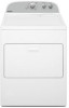
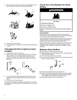
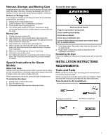
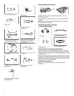
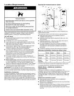
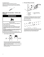
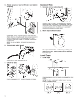
� If your dryer has been converted to use propane gas, 3/8" propane-compatible copper tubing can be used. If the total length of the supply line is more than 20 ft. (6.1 m), use larger pipe. NOTE: Pipe-joint compounds that resist the action of propane gas must be used. Do not use PTFE plumber's tape. � Must include shutoff valve. In the U.S.A.: An individual manual shutoff valve must be installed within six (6) ft. (1.8 m) of the dryer in accordance with the National Fuel Gas Code, ANSI Z223.1. The location should be easy to reach for opening and closing. In Canada: An individual manual shutoff valve must be installed in accordance with the B149.1, Natural Gas and Propane Installation Code. It is recommended that an individual manual shutoff valve be installed within six (6) ft. (1.8 m) of the dryer. The location should be easy to reach for opening and closing. INSTALLATION Install Leveling Legs WARNING Excessive Weight Hazard Use two or more people to move and install or uninstall appliance. Failure to do so can result in back or other injury. 1. Prepare dryer for leveling legs A. 3/8" flexible gas connector B. 3/8" pipe-to-flare adapter fitting C. 1/8" NPT minimum plugged tapping D. 1/2" NPT gas supply line E. Gas shutoff valve Gas Supply Connection Requirements � Use an elbow and a 3/8" flare x 3/8" NPT adapter fitting between the flexible gas connector and the dryer gas pipe, as needed to avoid kinking. � Use only pipe-joint compound. Do not use PTFE plumber's tape. � This dryer must be connected to the gas supply line with a listed flexible gas connector that complies with the standard for connectors for gas appliances, ANSI Z21.24 or CSA 6.10. Burner Input Requirements Elevations above 2,000 ft. (610 m) � When installed above 2,000 ft. (610 m), a 4% reduction of the burner Btu rating shown on the model/serial number plate is required for each 1,000 ft. (305 m) increase in elevation. Gas supply pressure testing � The dryer must be disconnected from the gas supply piping system during pressure testing at pressures greater than 1/2 psi (3.45 kPa). Dryer gas pipe � The gas pipe that comes out through the rear of your dryer has a 3/8" male pipe thread. To avoid damaging floor, use a large flat piece of cardboard from dryer carton; place under entire back edge of dryer. Firmly grasp dryer body (not console panel) and gently lay dryer down on cardboard. 2. Screw in leveling legs Leveling leg with diamond marking Leveling leg without diamond marking Using a wrench and tape measure, screw leveling leg into leg holes until bottom of foot is approximately 1/2" (13 mm) to 1 1/2" (38 mm) from bottom of the dryer. For leveling legs with the diamond marking: Screw legs into leg holes by hand. Use a wrench to finish turning legs until diamond marking is no longer visible. Place a carton corner post from dryer packaging under each of the two dryer back corners. Stand the dryer up. Slide the dryer on the corner posts until it is close to its final location. Leave enough room to connect the exhaust vent. 11
-
 1
1 -
2
-
3
-
4
-
5
-
 6
6 -
 7
7 -
 8
8 -
 9
9 -
 10
10 -
 11
11 -
 12
12 -
 13
13 -
 14
14 -
 15
15 -
 16
16 -
17
-
18
-
19
-
20
-
21
-
22
-
23
-
24
-
25
-
26
-
27
-
28
-
29
-
30
-
31
-
32
-
33
-
34
-
35
 |
 |
