Whirlpool WGD5800S Dimensions - Page 1
Whirlpool WGD5800S Manual
 |
View all Whirlpool WGD5800S manuals
Add to My Manuals
Save this manual to your list of manuals |
Page 1 highlights
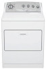
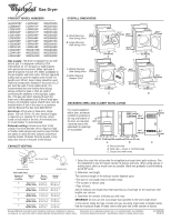
® Gas Dryer PRODUCT MODEL NUMBERS OVERALL DIMENSIONS GGW9878P LGB6000P LGB6200P LGB6300P LGN1000P LGQ9030P LGQ9508P LGQ9858P LGR3624P LGR4600P LGR4610P LGR5636P LGR5644P LGR6611P LGR6620P LGR6621P LGR6636P LGR6646P LGR7648P LGR8620P LGR8648P WGD5100S WGD5300S WGD5500S WGD5520S WGD5530S WGD5540S WGD5550S WGD5600S WGD5800S WGD5810S WGD5820S WGD5830S WGD5840S WGD5850S WGD5900S A. Small Opening Side-Swing Door B. Large Opening Side-Swing Door 43 ³⁄₈" (110 cm) *26" (66 cm) 15¹⁄₄" (38.74 cm) 43 ³⁄₈" (110 cm) 29" (73.66 cm) A *27 ³⁄₄" (70.5 cm) 22 ³⁄₄" (57.8 cm) 29" (73.66 cm) B Gas supply: This dryer is equipped for use with natural gas. It is designed-certified by CSA International for L.P. (propane or butane) gases with appropriate conversion. When rigid pipe is used it should be 1/2 inch IPS. When acceptable to the gas supplier and local codes, 3/8-inch approved tubing may be used for lengths under 20 feet. For lengths over 20 feet, larger tubing should be used. Pipe-joint compounds resistant to the action of L.P. gas must be used. If local codes permit, it is recommended that new flexible metal tubing, design-certified by AGA or CSA, be used for connecting the appliance to the rigid gas supply line. (The gas pipe which extends through the lower rear of the appliance has 3/8-inch male pipe thread.) An individual manual shutoff valve must be installed within 6 feet of the dryer in accordance with the National Fuel Gas Code ANSI Z223.1. Electrical: A four-wire or three-wire, single phase, 120-volt, 60 Hz, AC-only, electrical supply is required on a separate 15 or 20 amp circuit, fused on both sides of the line. A time-delay fuse or circuit breaker is recommended. Exhaust venting: Exhaust your dryer to the outside. Four-inch diameter vent is required. Rigid or flexible metal exhaust vent must be used. Do Not use plastic or metal foil vent. Exhaust outlet hood must be at least 12 inches from the ground or any object that may be in the path of the exhaust. EXHAUST VENTING C. Wided Opening 43 ³⁄₈" Side-Swing Door (110cm) D. Wide Opening Hamper Door *27 ³⁄₄" (70.5 cm) 22 ³⁄₄" (57.8 cm) 43³⁄₈" (110 cm) 29" (73.66 cm) C *27 ³⁄₄" (70.5 cm) 13 ³⁄₄" (34.9 cm) 29" (73.66 cm) D RECESSED AREA AND CLOSET INSTALLATION For closet installation with a door, minimum ventilation openings in the top and bottom of 18" the door are required. (45.7 cm) Louvered doors with equivalent air openings are acceptable. 14" max. (35.6 cm) 48 in. 2 (310 cm2 ) 24 in.2 (155 cm2 ) 1" 29" 1" 1" 27³⁄₄" 5¹⁄₂" (2.5 cm) (73.66 cm) (2.5 cm)(2.5 cm)(70.5 cm) (14 cm) A B A. Recessed area B. Side view - closet or confined area C. Closet door with vents 3" (7.6 cm) 3" (7.6 cm) C Box hood style 4" (10.2 cm) 4" (10.2 cm) Louvered style Vent Length Chart Number of 90° turns or elbows Type of vent Box or Louvered hoods 4" (10.2 cm) 2.5" (6.4 cm) Angled style Angled hoods 0 Rigid metal 64 ft (20 m) 58 ft (17.7 m) Flexible metal 36 ft (11 m) 28 ft (8.5 m) 1 Rigid metal 54 ft (16.5 m) 48 ft (14.6 m) Flexible metal 31 ft (9.4 m) 23 ft (7 m) 2 Rigid metal 44 ft (13.4 m) 38 ft (11.6 m) Flexible metal 27 ft (8.2 m) 19 ft (5.8 m) 3 Rigid metal 35 ft (10.7 m) 29 ft (8.8 m) Flexible metal 25 ft (7.6 m) 17 ft (5.2 m) 4 Rigid metal 27 ft (8.2 m) 21 ft (6.4 m) Flexible metal 23 ft (7 m) 15 ft (4.6 m) 1. Select the route that will provide the straightest and most direct path outdoors. Plan the installation to use the fewest number of elbows and turns. When using elbows or making turns, allow as much room as possible. Bend vent gradually to avoid kinking. Avoid 90° turns. 2. Determine vent length. The maximum length of the exhaust system depends upon: • The type of vent (rigid metal or flexible metal). • The number of elbows used. • Type of hood. See the exhaust vent length chart that matches your hood type for the maximum vent lengths you can use. 3. Determine the number of elbows you will need. IMPORTANT: Do not use vent runs longer than specified in the Vent Length Chart. In the column listing the type of metal vent you are using (rigid metal or flexible metal), find the maximum length of metal vent on the same line as the number of elbows. Because Whirlpool Corporation policy includes a continuous commitment to improve Dimensions are for planning purposes only. For complete details, see Installation our products, we reserve the right to change materials and specifications without notice. Instructions packed with product. Specifications subject to change without notice. Ref. 8562582 08-08-06
-
 1
1
 |
 |