Whirlpool WGG755S0BS Installation Guide - Page 10
Level Range, Electronic Ignition System - lowes
 |
View all Whirlpool WGG755S0BS manuals
Add to My Manuals
Save this manual to your list of manuals |
Page 10 highlights
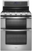
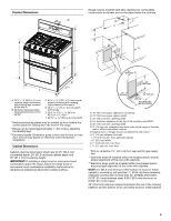
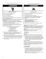
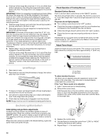
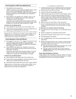
3. If the rear of the range lifts more than ½" (1.3 cm) off the floor without resistance, stop tilting the range and lower it gently back to the floor. The range foot is not engaged in the anti-tip bracket. IMPORTANT: If there is a snapping or popping sound when lifting the range, the range may not be fully engaged in the bracket. Check to see if there are obstructions keeping the range from sliding to the wall or keeping the range foot from sliding into the bracket. Verify that the bracket is held securely in place by the mounting screws. 4. Slide the range forward, and verify that the anti-tip bracket is securely attached to the floor or wall. 5. Slide range back so the rear range foot is inserted into the slot of the anti-tip bracket. IMPORTANT: If the back of the range is more than 2" (5.1 cm) from the mounting wall, the rear range foot may not engage the bracket. Slide the range forward and determine if there is an obstruction between the range and the mounting wall. Changes to the gas supply must be performed by a qualified service technician. If you need assistance or service, refer to the "Assistance or Service" section of the Use and Care Guide, or the cover or "Warranty" section of the User Instructions, for contact information. 6. Repeat steps 1 and 2 to ensure that the range foot is engaged in the anti-tip bracket. If the rear of the range lifts more than ½" (1.3 cm) off the floor without resistance, the anti-tip bracket may not be installed correctly. Do not operate the range without anti-tip bracket installed and engaged. Please reference the "Assistance or Service" section of the Use and Care Guide, or the cover or "Warranty" section of the User Instructions, to contact service. Level Range 1. Place rack in oven. 2. Place level on rack and check levelness of range, first side to side; then front to back. 3. If range is not level, pull range forward until rear leveling leg is removed from the anti-tip bracket. 4. Use wrench to adjust leveling legs up or down until range is level. Push range back into position. 5. Check that rear leveling leg is engaged in anti-tip bracket. NOTE: Range must be level for satisfactory baking performance. Electronic Ignition System Initial lighting and gas flame adjustments Cooktop and oven burners use pilotless igniters in place of standing pilots. When the cooktop control knob is turned to the "IGNITE" position, the system creates a spark to light the burner. This sparking continues, as long as the control knob is turned to "IGNITE." When the oven control is turned to the desired setting, a glow bar igniter heats and ignites the gas. Check Operation of Cooktop Burners Standard Surface Burners Push in and turn each control knob to the "IGNITE" position. The flame should light within 4 seconds. The first time a burner is lit, it may take longer than 4 seconds to light because of air in the gas line. If burners do not light properly: ■ Turn cooktop control knob to the "OFF" position. ■ Check that the range is plugged in and the circuit breaker has not tripped or the household fuse has not blown. ■ Check that the gas shutoff valve is set to the "open" position. ■ Check that burner caps are properly positioned on burner bases. Repeat start-up. If a burner does not light at this point, turn the control knobs to "OFF" and contact your dealer or authorized service company for assistance. Adjust Flame Height Adjust the height of top burner flames. The cooktop "Low" burner flame should be a steady blue flame approximately ¼" (0.64 cm) high. A B A. Low flame B. High flame To adjust standard burners: The flame can be adjusted using the adjustment screw in the center of the valve stem. The valve stem is located directly underneath the control knob. If the "Low" flame needs to be adjusted: 1. Light 1 burner and turn to lowest setting. 2. Remove the control knob. Hold the knob stem in the low position using a pair of pliers. Use a ¹⁄₈" (3.0 mm) flat-blade screwdriver to turn the screw located in the center of the control knob stem until the flame is the proper size. 3. Replace the control knob. 4. Test the flame by turning the control from "LOW" to "HIGH," checking the flame at each setting. 5. Repeat steps 1 - 4 for each burner. 10
-
 1
1 -
2
-
3
-
4
-
 5
5 -
 6
6 -
 7
7 -
 8
8 -
 9
9 -
 10
10 -
 11
11 -
 12
12 -
 13
13 -
 14
14 -
 15
15 -
16
-
17
-
18
-
19
-
20
-
21
-
22
-
23
-
24
-
25
-
26
-
27
-
28
-
29
-
30
-
31
-
32
-
33
-
34
-
35
-
36
-
37
-
38
-
39
-
40
 |
 |