Whirlpool WGT3300XQ Dimension Guide - Page 2
Drain System, Electrical Requirements, Venting Requirements - parts
 |
View all Whirlpool WGT3300XQ manuals
Add to My Manuals
Save this manual to your list of manuals |
Page 2 highlights
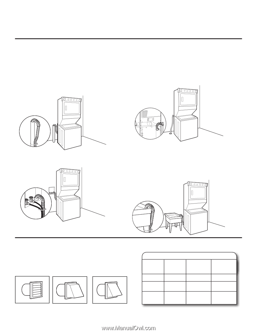
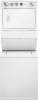
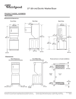
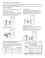
ELECTRICAL REQUIREMENTS To supply the required 3 or 4 wire, single phase, 120/240 volt, 60 Hz., AC only electrical supply (or 3 or 4 wire, 120/208 volt electrical supply, if specified on the serial/rating plate) on a separate 30-amp circuit, fused on both sides of the line. A time-delay fuse or circuit breaker is recommended. Connect to an individual branch circuit. DRAIN SYSTEM Drain system can be installed using a floor drain, wall standpipe, floor standpipe, or laundry tub. Select method you need. Floor standpipe drain system Minimum diameter for a standpipe drain: 2" (51 mm). Minimum carry-away capacity: 17 gal. (64 L) per minute. Top of standpipe must be at least 39" (990 mm) high; install no higher than 96" (2.4 m) from bottom of washer/dryer. If you must install higher than 96" (2.4 m), you will need a sump pump system. Floor drain system Floor drain system requires a Siphon Break Kit (Part Number 285834), 2 Connector Kits (Part Number 285385), and an Extension Drain Hose (Part Number 285863) that may be purchased separately. See "Use and Care Guide" for ordering details. Minimum siphon break: 28" (710 mm) from bottom of washer/dryer. (Additional hoses may be needed.) Wall standpipe drain system See requirements for floor standpipe drain system. Laundry tub drain system Minimum capacity: 20 gal. (76 L). Top of laundry tub must be at least 39" (990 mm) above floor; install no higher than 96" (2.4 m) from bottom of washer/dryer. IMPORTANT: To avoid siphoning, no more than 4.5" (113 mm) of drain hose should be inside standpipe or below the top of wash tub. Secure drain hose with shipping strap. VENTING REQUIREMENTS Exhaust venting: Exhaust your dryer to the outside. 4" (102 mm) diameter vent is required. Rigid or flexible metal exhaust vent must be used. Do not use plastic or metal foil vet. Exhaust hood must be at least 12" (305 mm) from the ground or any object that may be in the path of the exhaust. Recommended Styles: Acceptable Style: Louvered hood Box hood Angled hood The "Vent System Chart" provides venting requirements that will help achieve best drying performance. Number of 90° turns or elbows Vent System Chart Type Box/louvered of vent hoods Angled hoods 0 Rigid metal 37 ft. (11.3 m) 35 ft. (10.7 m) 1 Rigid metal 32 ft. (9.7 m) 27 ft. (8.2 m) 2 Rigid metal 24 ft. (7.3 m) 19 ft. (5.8 m) NOTE: Side exhaust installations have a 90º turn inside the dryer. To determine maximum exhaust length, add one 90º turn to the chart.
-
 1
1 -
 2
2
 |
 |