Whirlpool WHD3090G Dimension Guide - Page 2
Drain System, Electrical Requirements
 |
View all Whirlpool WHD3090G manuals
Add to My Manuals
Save this manual to your list of manuals |
Page 2 highlights
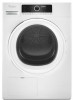
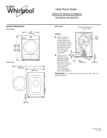
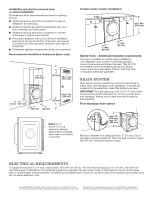
Installation spacing for recessed area or closet installation All dimensions show recommended and minimum spacing allowed. ■■ Additional spacing should be considered for ease of installation and servicing. ■■ Additional clearances might be required for wall, door, floor, moldings, and drain system. ■■ Additional spacing should be considered on all sides of the dryer to reduce noise transfer. ■■ For closet installation with a door, minimum ventilation openings in the top and bottom of the door are required. Louvered doors with equivalent ventilation openings are acceptable. ■■ Companion appliance spacing should also be considered. Recommended installation clearances (dryer only): 18" min. (457 mm) 3" (76 mm) 48 in.2 min. (310 cm2) 0" - 5"* (0 mm - 127 mm) 24 in.2 min. (155 cm2) 3" (76 mm) 1" 1" (25 mm) (25 mm) *NOTE: 0"-5" (0 mm-127 mm) spacing is allowed behind dryer, providing drain hose is not kinked or pinched. Custom under-counter installation: 0" Min. (0 mm) 341⁄2" Min. (876 mm) 1" Min. (25 mm) 1" Min. (25 mm) Mobile home - Additional installation requirements: This dryer is suitable for mobile home installations. The installation must conform to the Manufactured Home Construction and Safety Standard, Title 24 CFR, Part 3280 (formerly the Federal Standard for Mobile home construction and Safety, Title 24, HUD Part 280) or Standard CAN/CSA-Z240 MH. DRAIN SYSTEM Drain system can be installed by routing the white hose to a floor drain, wall standpipe, floor standpipe, or laundry tub instead of to the water tank. Select the method you need. IMPORTANT: To avoid siphoning, only 4.5" (114 mm) of drain hose should be inside standpipe; do not force excess hose into standpipe. Always secure drain hose with a cable tie (not supplied). Floor standpipe drain system 4.5" (114 mm) max. 3468" ((1921109mmmm)) min. 30" (762 mm) Minimum diameter for a standpipe drain: 2" (51 mm). Top of standpipe must be at least 30" (762 mm) high; install no higher than 36" (910 mm) from bottom of dryer. ELECTRICAL REQUIREMENTS To supply the required 3- or 4-wire, single-phase, 120-/240-volt, 60 Hz., AC-only electrical supply (or 3- or 4-wire, 120-/208-volt electrical supply, if specified on the serial/rating plate) on a separate 30-amp circuit, fused on both sides of the line. A time-delay fuse or circuit breaker is recommended. Connect to an individual branch circuit. Do not have a fuse in the neutral or grounding circuit. Do not use an extension cord. Because Whirlpool Corporation policy includes a continuous commitment to improve our products, we reserve the right to change materials and specifications without notice. Dimensions are for planning purposes only. For complete details, see Installation Instructions packed with product. Specifications subject to change without notice.
-
 1
1 -
 2
2
 |
 |
