Whirlpool WMH32519HZ Installation Instructions - Page 13
Venting Design Specifications
 |
View all Whirlpool WMH32519HZ manuals
Add to My Manuals
Save this manual to your list of manuals |
Page 13 highlights
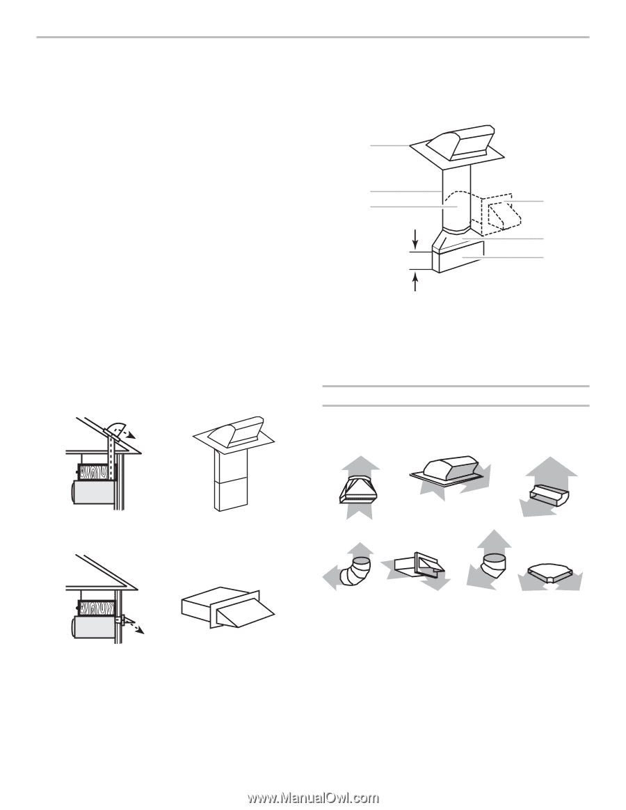
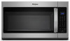
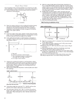
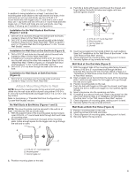
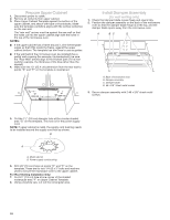
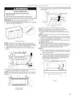
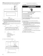
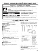
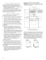
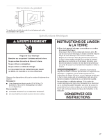
VENTING DESIGN SPECIFICATIONS This section is intended for architectural designer and builder/ contractor reference only. NOTES: ■■ Vent materials needed for installation are not provided with microwave hood combination. ■■ We do not recommend using a flexible metal vent. ■■ To avoid possible product damage, be sure to vent air outside, unless using recirculation installation. Do not vent exhaust air into concealed spaces, such as spaces within walls or ceilings, attics, crawl spaces or garages. For optimal venting installation, we recommend: ■■ Using roof or wall caps that have backdraft dampers. ■■ Using a rigid metal vent. ■■ Using the most direct route by minimizing the length of the vent and number of elbows to provide efficient performance. ■■ Using uniformly sized vents. ■■ Using duct tape to seal all joints in the vent system. ■■ Using caulking compound to seal exterior wall or roof opening around cap. ■■ Not installing 2 elbows together, for optimal hood performance. If venting through the wall, be sure that there is proper clearance within the wall for the damper to open fully. If venting through the roof, and rectangular-to-round transition is used, be sure there are at least 3" (7.6 cm) of clearance between the top of the microwave oven and the transition piece. See "Rectangular-to-Round Transition" illustration. Rectangular-to-Round Transition NOTE: The minimum 3" (7.6 cm) clearance must exist between the top of the microwave oven and the rectangular-to-round transition piece so that the damper can open freely and fully. A B C D E 3" (7.6 cm) F A. Roof cap B. 6" (15.2 cm) min. diameter round vent C. Elbow (for wall venting only) D. Wall cap E. 31⁄4" x 10" to 6" (8.3 x 25.4 cm to 15.2 cm) rectangular-to-round transition piece F. Vent extension piece, at least 3" (7.6 cm) high Recommended Standard Fittings The following length equivalents are for use when figuring vent length. See the examples in "Recommended Vent Length." A B C Roof venting Roof cap Wall venting Wall cap D E F G A. Rectangular-to-round transition piece: 31⁄4" x 10" to 6" = 5 ft (8.3 x 25.4 cm to 15.2 cm = 1.5 m) B. Roof cap: 31⁄4" x 10" = 24 ft (8.3 x 25.4 cm = 7.3 m) C. 90° elbow: 31⁄4" x 10" = 25 ft (8.3 x 25.4 cm = 7.6 m) D. 90° elbow: 6" = 10 ft (15.2 cm = 3 m) E. Wall cap: 31⁄4" x 10" = 40 ft (8.3 x 25.4 cm = 12.2 m) F. 45° elbow: 6" = 5 ft (15.2 cm = 1.5 m) G. 90° flat elbow: 31⁄4" x 10" = 10 ft (8.3 x 25.4 cm = 3 m) 13
-
 1
1 -
2
-
3
-
4
-
5
-
6
-
7
-
 8
8 -
 9
9 -
 10
10 -
 11
11 -
 12
12 -
 13
13 -
 14
14 -
 15
15 -
 16
16 -
 17
17 -
 18
18 -
19
-
20
-
21
-
22
-
23
-
24
-
25
-
26
-
27
-
28
 |
 |