Whirlpool WML75011H Installation Instructions - Page 8
Mark Rear Wall, Drill Holes in Rear Wall
 |
View all Whirlpool WML75011H manuals
Add to My Manuals
Save this manual to your list of manuals |
Page 8 highlights
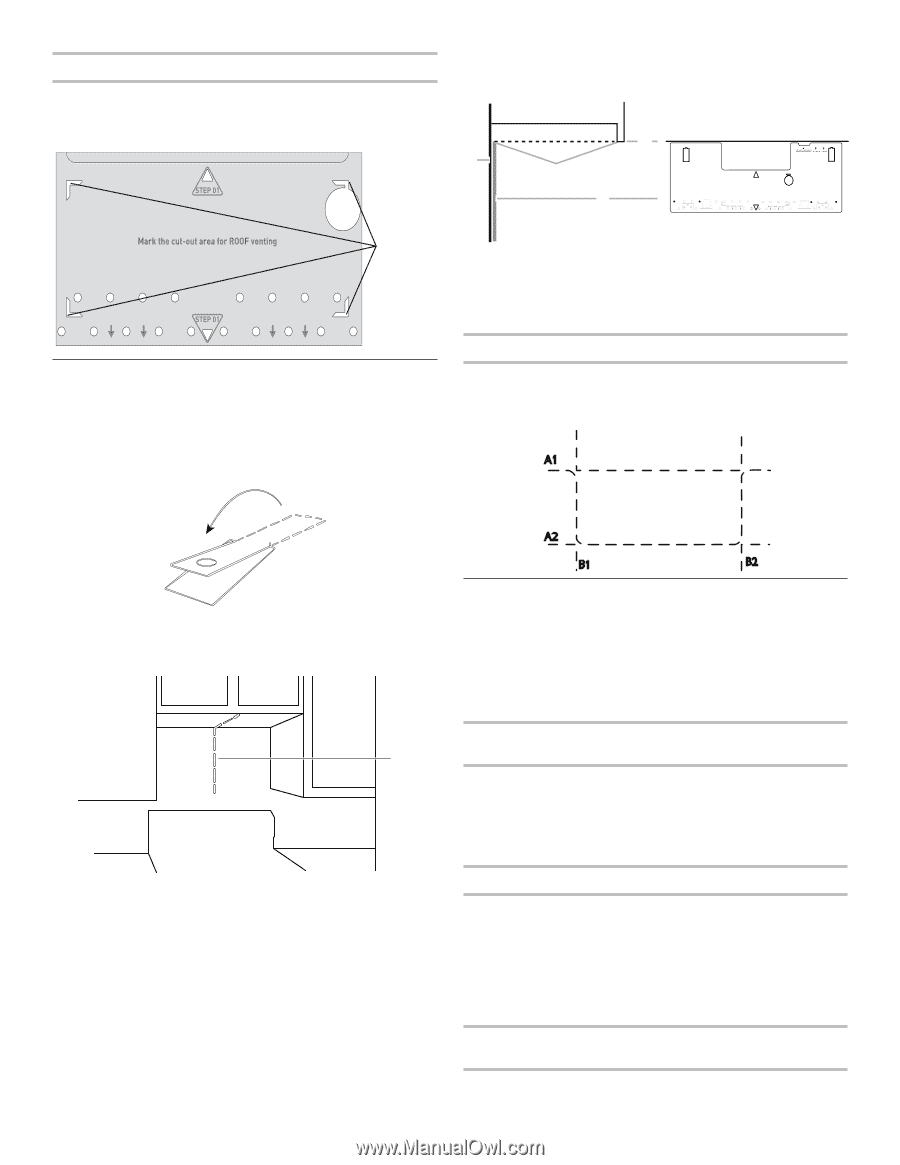
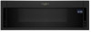
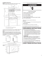
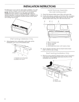
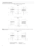
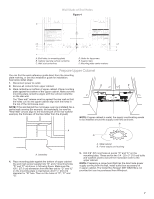
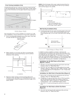
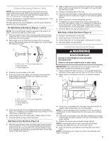
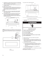
Roof Venting Installation Only If venting through the roof, mark and trace the corner punches on the mounting plate. Set mounting plate aside, cut the venting area out from the bottom of the upper cabinet using a keyhole saw. NOTE: If the front edge of the upper cabinet is lower than the back edge, lower the mounting plate so that its top is leveled with the front edge of the cabinet. D A C B 4 Corners REAR WALL REAR WALL Mark Rear Wall The microwave oven must be installed on a minimum of 1 wall stud, preferably 2, using a minimum of 1 lag screw, preferably 2. 1. Fold 2 mounting tabs forward into the tab cutout. Note that the tabs will NOT be flush after folding. Fold Forward 2. Mark centerline on the back wall. Place mounting plate against the back wall, find and clearly mark the vertical centerline of the opening. A A. Centerline 3. Align the center markers on the mounting plate to the centerline of the wall. Make sure it is leveled and top of the mounting plate is butted up against the bottom edge of the upper cabinet. 8 A. Rear wall B. Mounting plate C. Top of mounting plate must align with front edge of cabinet D. Front edge of upper cabinet Wall Venting Installation Only 4. If venting through the wall, place mounting plate on the wall and mark the cut-out area. Set mounting plate aside, then using a keyhole saw, cut out hole in the wall at back venting area. A1 Cut-out area for BACK WALL Venting A2 B1 B2 Drill Holes in Rear Wall In addition to being installed on at least 1 wall stud, the mounting plate must attach to the wall at both end holes. If the end holes are not over wall studs, use two 3/16-24 x 3" (7.6 cm) round head bolts with toggle nuts; if 1 end hole is over a wall stud, use 1 lag screw and one 3/16-24 x 3" (7.6 cm) round-head bolt with toggle nut; or if both end holes are over wall studs, use 2 lag screws. Following are 3 installation configurations. Installation for No Wall Studs at End Holes (Figures 1 and 2) 1. Drill 5/8" (1.6 cm) holes through the wall at both end holes marked in Step 3 of "Mark Rear Wall." 2. Drill 3/16" (5 mm) hole(s) into the wall stud(s) at the hole(s) marked in Step 6 of "Mark Rear Wall." Refer to figures 1 and 2 in "Possible Wall Stud Configurations" in the "Locate Wall Stud(s)" section. Installation for Wall Stud at One End Hole (Figure 3) 1. Drill a 3/16" (5 mm) hole into the wall stud at the end hole marked in Step 3 of "Mark Rear Wall." 2. If installing on a second wall stud, drill a 3/16" (5 mm) hole into the wall stud at the other hole marked in Step 6 of "Mark Rear Wall." Refer to Figure 3 in "Possible Wall Stud Configurations" in the "Locate Wall Stud(s)" section. 3. Drill a 5/8" (1.6 cm) hole through the wall at the other end hole. Installation for Wall Studs at Both End Holes (Figure 4) 1. Drill 3/16" (5 mm) hole into the wall stud at the end hole marked in Step 3 of "Mark Rear Wall."
-
 1
1 -
2
-
 3
3 -
 4
4 -
 5
5 -
 6
6 -
 7
7 -
 8
8 -
 9
9 -
 10
10 -
 11
11 -
 12
12
 |
 |