Whirlpool YWMH31017HS Installation Instructions - Page 11
Prepare Upper Cabinet, Install Damper Assembly
 |
View all Whirlpool YWMH31017HS manuals
Add to My Manuals
Save this manual to your list of manuals |
Page 11 highlights
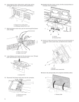
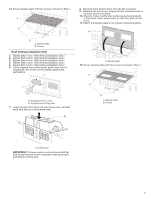
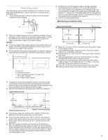
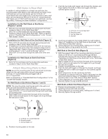
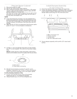
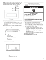
Prepare Upper Cabinet 1. Disconnect power to outlet. 2. Remove all contents from upper cabinet. 3. Place cardboard template against the bottom of the upper cabinet, make sure the template centerline aligns with the vertical centerline on the rear wall. The "rear wall" arrows must be against the rear wall so that the holes cut into the upper cabinet align with the holes in the top of the microwave oven. NOTE: ■ If the wall behind the microwave oven (as installed) has a partial wall covering (for example, tile backsplash), be sure the "Rear Wall" arrows align to the thickest part of the rear wall (for example, the thickness of the tiles rather than the drywall). 4. Make sure the 10" (25.4 cm) dimension from the rear wall to points "D" and "E" on the template is maintained. Install Damper Assembly (for wall venting only) 1. Check that damper blade moves freely and opens fully. 2. Position the damper assembly on the back of the microwave oven so that the damper blade hinge is at the top, and the damper blade opens away from the microwave oven. A B C D D 10" (25.4 cm) F Rear Wall E 10" G (25.4 cm) Mur arrière A. Back of microwave oven B. Damper assembly C. Damper blade D. #6 x 3/8" Sheet metal screws 3. Secure damper assembly with two #6 x 3/8" sheet metal screws. 5. Cut the 11⁄2" (3.8 cm) diameter hole at the circular shaded area "G" on the template. This hole is for the power supply cord. NOTE: If upper cabinet is metal, the supply cord bushing needs to be installed around the supply cord hole as shown. B A A. Metal cabinet B. Power supply cord bushing 6. Drill 3/8" (10 mm) holes at points "D" and "E" on the template. These are for two 1/4-20 x 3" bolts and washers used to secure the microwave oven to the upper cabinet. For Roof Venting Installation Only: 7. Cut 3/4" (1.9 cm) hole at one corner of the shaded rectangular area "F" on Cardboard Template. 8. Using a keyhole saw, cut out the rectangular area. 11
-
 1
1 -
2
-
3
-
4
-
5
-
 6
6 -
 7
7 -
 8
8 -
 9
9 -
 10
10 -
 11
11 -
 12
12 -
 13
13 -
 14
14 -
 15
15 -
 16
16 -
17
-
18
-
19
-
20
-
21
-
22
-
23
-
24
-
25
-
26
-
27
-
28
-
29
-
30
-
31
-
32
 |
 |
