| Section |
Page |
| Cover Page |
1 |
| PHASER® 7300 COLOR PRINTER |
3 |
| Front Matter |
3 |
| Safety Terms |
5 |
| Manual Terms |
5 |
| Product Terms: |
5 |
| Power Safety Precautions |
6 |
| Power Source |
6 |
| Disconnecting Power |
6 |
| Electrostatic Discharge (ESD) Precautions |
7 |
| Service Safety Summary |
8 |
| General Guidelines |
8 |
| Warning Labels |
8 |
| Safety Interlocks |
8 |
| Servicing Electrical Components |
9 |
| Servicing Mechanical components |
9 |
| Servicing Fuser Components |
9 |
| Regulatory�Information |
10 |
| Declaration of Conformity |
11 |
| In the European Union |
11 |
| Canadian Notice |
12 |
| Avis Canadien |
12 |
| European Notice |
12 |
| Hinweis |
12 |
| Table of Contents |
13 |
| General Information |
17 |
| Contents |
17 |
| The Phaser 7300 Color Printer Overview |
18 |
| Phaser 7300 Printer Configurations |
19 |
| Secure Prints, Proof Prints, Saved Prints and PDF Direct Printing |
20 |
| Power Saver Mode |
20 |
| Printer Memory and RAM Capabilities |
21 |
| Parts of the Printer |
22 |
| Print Engine Base Configuration |
22 |
| Printer Options - Lower Tray Deck (LTD) and Lower Tray Assembly (LTA) |
23 |
| Printer Options (cont’d) - Duplex Unit |
24 |
| 1. Duplex Unit |
24 |
| Front Panel Configuration |
25 |
| Front Panel LED indicators: |
25 |
| Image Processor (IP) Board Components |
26 |
| 1 |
26 |
| 2 |
26 |
| 3 |
26 |
| 4 |
26 |
| 5 |
26 |
| 6 |
26 |
| Rear Panel Configuration of the IP Board |
27 |
| DIP Switches |
28 |
| Printer Specifications |
29 |
| Physical Dimensions - Print Engine |
29 |
| Physical Dimensions - Options |
29 |
| Printer Clearances |
29 |
| Functional Specifications |
30 |
| Print Speeds |
30 |
| Electrical Specifications |
31 |
| Environmental Specifications (cont'd.) |
31 |
| Media and Tray Specifications (cont'd.) |
32 |
| Error Messages and Codes |
35 |
| Accessing Error Codes and Fault History |
35 |
| 1. Print (if possible) the Usage Profile Report Log from the printer’s front panel Support Menu. ... |
35 |
| 2. View the printer’s fault history on the front panel. |
35 |
| 3. If the printer is connected to a network and has a TCP/IP address, view the printer’s web page... |
35 |
| Error Messages and Codes Index |
36 |
| Service Flowchart |
40 |
| 1 Verify the reported problem does exist. |
40 |
| 2 Check for any error codes and write them down. |
40 |
| 3 Print normal customer prints and service test prints. |
40 |
| 4 Make note of any print quality problems in the test prints. |
40 |
| 5 Make note of any mechanical or electrical abnormalities present. |
40 |
| 6 Make note of any unusual noise or smell coming from the printer. |
40 |
| 7 Print a Usage Profile Report, if the printer is able to print. |
40 |
| 8 View the fault history under the Service Tools Menu |
40 |
| 9 Verify the AC input power supply is within proper specifications by measuring the voltage at th... |
40 |
| 1 Switch OFF printer power. |
40 |
| 2 Disconnect the AC power cord from the wall outlet. |
40 |
| 3 Verify the power cord is free from damage or short circuit and is connected properly. |
40 |
| 4 Remove the Imaging Unit and protect it from light. |
40 |
| 5 Inspect the printer interior and remove any foreign matter such as paper clips, staples, pieces... |
40 |
| 6 Clean all rubber rollers with a lint-free cloth, dampened slightly with cold water and mild det... |
40 |
| 7 Inspect the interior of the printer for damaged wires, loose connections, toner leakage, and da... |
40 |
| 8 If a toner cartridge appears obviously damaged, replace with a new one. |
40 |
| 1 Use the Error Messages and Codes and troubleshooting procedures to find the cause of the problem. |
40 |
| 2 Use Diagnostics to check printer and optional components. |
40 |
| 3 Use the Wiring Diagrams to locate test points. |
40 |
| 4 Take voltage readings at various test points as instructed in the appropriate troubleshooting p... |
40 |
| 5 Use the Service Test Prints to isolate problems with the Image Processor Board. |
40 |
| 1 Use the Parts List to locate a part number |
40 |
| 2 Use the Removal and Replacement Procedures to replace the part. |
40 |
| 1 Test the printer to be sure you have corrected the initial problem and there are no additional ... |
40 |
| Using the Troubleshooting Procedures |
41 |
| 1. Each Step in a Troubleshooting Procedure instructs you to perform a certain action or procedur... |
41 |
| 2. The Actions and Questions box contains additional information and/or additional procedures you... |
41 |
| 3. When a procedure instructs you to test a component using service diagnostics, See “Service Dia... |
41 |
| 4. The action is followed by a question. If your response to the question is “Yes”, then follow t... |
41 |
| 5. Troubleshooting Procedures may ask you to take voltage readings or test for continuity at cert... |
41 |
| 6. Troubleshooting Procedures often ask you to replace a printer component. The section \ |
41 |
| General Notes on Troubleshooting |
41 |
| 1. Unless indicated otherwise, the instruction “cycle power to the printer” means for you to swit... |
41 |
| 2. When instructed to take voltage, continuity or resistance readings on wiring harnesses, refer ... |
41 |
| 3. All voltage values given in the troubleshooting procedures are approximate values. The main pu... |
41 |
| 4. When a troubleshooting procedure instructs you to replace a non-spared component and that comp... |
41 |
| Service Diagnostics |
42 |
| Enter without rebooting the printer (Hidden Service Menu): |
42 |
| 1. From the printer’s main menu, scroll to the Support Menu, press OK and then scroll to the Serv... |
42 |
| 2. Hold down the Up Arrow key and press the Down Arrow key. |
42 |
| 3. Scroll to Run Diagnostics and press OK. |
42 |
| Enter by rebooting the printer: |
42 |
| 1. Turn the printer power OFF. |
42 |
| 2. Hold down the Back and Information keys simultaneously and turn the printer back ON. |
42 |
| 3. Continue to hold the keys until the following message is displayed on the front panel: Service... |
42 |
| 4. The front panel displays the Service Diagnostics Menu. |
42 |
| Service Diagnostics Key Press and Function Table |
42 |
| Service Diagnostics Tests and Functions Table (cont'd.) |
43 |
| Error Messages and Codes Procedures |
53 |
| Jam at Top Cover |
53 |
| 1 |
53 |
| 2 |
53 |
| 3 |
53 |
| 4 |
53 |
| 5 |
53 |
| 6 |
54 |
| 7 |
54 |
| 8 |
54 |
| 9 |
54 |
| 10 |
54 |
| 11 |
54 |
| Jam at Door [A] [B] [C] [D] [E] |
55 |
| 1 |
55 |
| 2 |
55 |
| 3 |
55 |
| 4 |
55 |
| 5 |
55 |
| 6 |
55 |
| 7 |
55 |
| 8 |
55 |
| 9 |
55 |
| 10 |
56 |
| 11 |
56 |
| 12 |
56 |
| 13 |
56 |
| 14 |
56 |
| 15 |
56 |
| 16 |
56 |
| 17 |
56 |
| Jam at Duplex Unit |
57 |
| 1 |
57 |
| 2 |
57 |
| 3 |
57 |
| 4 |
57 |
| 5 |
57 |
| 6 |
57 |
| Misfeed at Tray [1] [2] [3] [4] [5] |
58 |
| 1 |
58 |
| 2 |
58 |
| 3 |
58 |
| 4 |
58 |
| 5 |
58 |
| 6 |
58 |
| Insert Tray [1] [2] [3] [4] [5] |
59 |
| 1 |
59 |
| 2 |
59 |
| 3 |
59 |
| 4 |
59 |
| E12: Top Output Tray is Full, Unload Paper |
59 |
| 1 |
59 |
| 2 |
59 |
| 3 |
59 |
| 4 |
59 |
| MPT Empty, Load Paper |
60 |
| 1 |
60 |
| 2 |
60 |
| 3 |
60 |
| 4 |
60 |
| Tray [1] [2] [3] [4] [5] Empty, Load Paper |
60 |
| 1 |
60 |
| 2 |
60 |
| 3 |
60 |
| 4 |
60 |
| Load MPT with [size*] [type*] |
61 |
| 1 |
61 |
| 2 |
61 |
| 3 |
61 |
| 4 |
61 |
| 5 |
61 |
| 6 |
61 |
| Load Tray [1] [2] [3] [4] [5] with [size*] [type*] |
62 |
| 1 |
62 |
| 2 |
62 |
| 3 |
62 |
| 4 |
62 |
| 5 |
62 |
| 6 |
62 |
| 7 |
62 |
| 8 |
62 |
| Adjust Tray [1] [2] [3] [4] [5] Size |
63 |
| 1 |
63 |
| 2 |
63 |
| 3 |
63 |
| 4 |
63 |
| 5 |
63 |
| 6 |
63 |
| Close Top Cover |
64 |
| 1 |
64 |
| 2 |
64 |
| 3 |
64 |
| 4 |
64 |
| 5 |
64 |
| 6 |
64 |
| 7 |
64 |
| Close Duplex Unit |
65 |
| 1 |
65 |
| 2 |
65 |
| 3 |
65 |
| 4 |
65 |
| 5 |
65 |
| Close Right Door A |
65 |
| 1 |
65 |
| 2 |
65 |
| 3 |
65 |
| 4 |
65 |
| Close Right Door [B] [C] [D] [E] |
66 |
| 1 |
66 |
| 2 |
66 |
| 3 |
66 |
| 4 |
66 |
| Open Left Side Output Tray |
66 |
| 1 |
66 |
| 2 |
66 |
| 3 |
66 |
| Humidity Too High to Print |
67 |
| 1 |
67 |
| 2 |
67 |
| Install or Reseat [CMYK] Imaging Unit |
68 |
| 1 |
68 |
| 2 |
68 |
| 3 |
68 |
| 4 |
68 |
| 5 |
68 |
| 6 |
68 |
| Replace [CMYK] Imaging Unit |
68 |
| 1 |
68 |
| 2 |
68 |
| 3 |
68 |
| Install or Reseat [CMYK] Toner Cartridge |
69 |
| 1 |
69 |
| 2 |
69 |
| 3 |
69 |
| 4 |
69 |
| 5 |
69 |
| 6 |
69 |
| Replace [CMYK] Toner Cartridge |
69 |
| 1 |
69 |
| 2 |
69 |
| 3 |
69 |
| 4 |
69 |
| Install or Reseat Fuser |
70 |
| 1 |
70 |
| 2 |
70 |
| Replace Fuser |
70 |
| 1 |
70 |
| 2 |
70 |
| Install or Reseat Transfer Unit |
71 |
| 1 |
71 |
| 2 |
71 |
| Replace Transfer Unit |
71 |
| 1 |
71 |
| 2 |
71 |
| 3 |
71 |
| T1: Fuser Upper Failure T2: Fuser Lower Failure |
72 |
| 1 |
72 |
| 2 |
72 |
| 3 |
72 |
| 4 |
72 |
| T29: Temp Sensor Failure |
72 |
| 1 |
72 |
| T30: RH Sensor Failure |
73 |
| 1 |
73 |
| T32: LED Over Temperature Failure |
73 |
| 1 |
73 |
| 1 |
73 |
| T34: IU Motor Overheating Failure |
73 |
| 1 |
73 |
| 2 |
73 |
| U0: Engine ROM Failure U1: Engine RAM Failure U2: Engine EEPROM Failure U3: Engine EEPROM Missing... |
74 |
| 1 |
74 |
| 2 |
74 |
| U6: Power Supply Failure |
74 |
| 1 |
74 |
| 2 |
74 |
| 3 |
74 |
| 4 |
74 |
| U7: Feeder Home Failure |
75 |
| 1 |
75 |
| 2 |
75 |
| 3 |
75 |
| 4 |
75 |
| U8: Controller Fan Failure (Electrical Card Cage) |
75 |
| 1 |
75 |
| 2 |
75 |
| 3 |
75 |
| U9: Power Supply Fan Failure |
76 |
| 1 |
76 |
| 2 |
76 |
| 3 |
76 |
| U12: Duplex Interface Failure |
76 |
| 1 |
76 |
| 2 |
76 |
| 3 |
76 |
| Tray [2] [3] [4] [5] Interface Failure |
77 |
| 1 |
77 |
| 2 |
77 |
| [Yellow] [Magenta] [Cyan] [Black] LED Failure |
77 |
| 1 |
77 |
| 2 |
77 |
| 3 |
77 |
| 4 |
77 |
| [Yellow] [Magenta] [Cyan] [Black] Imaging Unit Failure |
78 |
| 1 |
78 |
| 2 |
78 |
| 3 |
78 |
| 4 |
78 |
| 5 |
78 |
| 6 |
78 |
| 7 |
78 |
| 8 |
78 |
| 9 |
79 |
| 10 |
79 |
| 11 |
79 |
| U30: Flash Hardware Failure U31: Flash Software Failure |
79 |
| 1 |
79 |
| U32: Fuser Fan Failure |
79 |
| 2 |
79 |
| 3 |
79 |
| 4 |
79 |
| U33: Fuser 110v/220v Mismatch Failure |
80 |
| 1 |
80 |
| U34: Unsupported Duplex Unit ROM Failure |
80 |
| 1 |
80 |
| 2 |
80 |
| Unsupported Tray [2] [3] [4] [5] ROM Failure |
80 |
| 1 |
80 |
| W16: Fuse Cut Error in Fuser |
81 |
| 1 |
81 |
| 2 |
81 |
| W17: Fuse Cut Error in Transfer Unit |
81 |
| 1 |
81 |
| 2 |
81 |
| Fuse Cut Error in [CMYK] Imaging Unit |
81 |
| 1 |
81 |
| 2 |
81 |
| 3 |
81 |
| Troubleshooting |
83 |
| Contents |
83 |
| System Boot Sequence |
84 |
| 1. When the main power switch is turned on, the health LED on the Image Processor Board turns on ... |
84 |
| 2. The boot loader checks for RAM presence and functionality. If not present or functioning, it p... |
84 |
| 3. The boot loader then runs POST diagnostics. |
84 |
| 4. POST turns off the health LED. |
84 |
| 5. POST checks the front panel. |
84 |
| 6. If keys have been pushed, the front panel displays “Processing Input”. |
84 |
| 7. The front panel LED cycles: Green, Yellow, Red, and then off. |
84 |
| 8. The front panel turns on, the LED turns Green and the POST tests are finished. |
84 |
| Power On Self Test (POST) |
84 |
| POST Startup indications |
84 |
| POST Faults |
85 |
| Fault Reporting Devices |
85 |
| LED Blink Patterns |
85 |
| POST Diagnostics Test Descriptions |
86 |
| Printer Malefactions or Inoperable Printer Problems |
87 |
| No Front Panel Display After Power Switch is Turned ON. |
87 |
| 1. Verify the AC power source, see “Measuring Power Supply Voltages” on page�3-72. |
87 |
| 2. Verify the +5 volt loop is complete, see “The +5 VDC Loop” on page�3-74. |
87 |
| 3. If the front panel has no display, backlighting or LED, replace the Front Panel and Wiring Har... |
87 |
| 4. Check the Image Processor Board health LED for a front panel fault, see “POST Diagnostics Test... |
87 |
| 5. Verify the Image Processor Board has not failed by performing Step 3 from the troubleshooting ... |
87 |
| 6. Systematically remove all printer options to isolate a possible problem component. |
87 |
| The Printer Continuously Displays “Booting”, “Initializing” “Warming Up”, or will not come to a “... |
87 |
| 1. Check for unreported jams within the printer and clear the jam area. |
87 |
| 2. Power cycle the printer. |
87 |
| 3. Verifying Image Processor Board failure: |
87 |
| Verifying Power Supply Operation |
88 |
| Measuring Power Supply Voltages |
88 |
| 1. AC Input: With the DMM set to measure AC voltages, measure for power being supplied to the pri... |
88 |
| 2. DC Output: With the DMM set to measure DC voltages, measure the voltages at the POWER connecto... |
88 |
| POWER Connector Pinout |
88 |
| Safety interlocks |
89 |
| The +5 VDC Loop |
90 |
| To verify the +5 volt loop is complete: |
90 |
| 1. Test fuse F6 on the Engine Controller Board for continuity. If the fuse is blown (open circuit... |
90 |
| 2. Verify all wiring harnesses are connected, seated correctly and not damaged. Replace any damag... |
90 |
| 3. Check for continuity between the Engine Controller Board OPTN and the interconnect wiring harn... |
90 |
| 4. Verify proper operation of the LVPS by bypassing the Engine Controller Board and the toner sen... |
90 |
| 5. Replace the Low Voltage Power Supply if all other components are operating correctly. |
90 |
| Fuser Roller Resistances |
91 |
| Multi-Sheet Pick |
92 |
| 1. Ensure the correct weight and type of media is loaded in the tray. See \ |
92 |
| 2. Verify that the media settings at the front panel and the driver settings match the media load... |
92 |
| 3. Fan the media and reload into the tray. |
92 |
| 4. Use service diagnostics to verify the printer is printing within its environmental specificati... |
92 |
| 5. Ensure the media is correctly loaded in the tray and that the guides fit snug against the media. |
92 |
| 6. Clean the pick and feed rollers with a clean, dry, lint-free wipe if debris is visible. Check ... |
92 |
| Media Skewing |
92 |
| 1. Ensure the correct weight and type of media is loaded in the tray. See \ |
92 |
| 2. Make sure that the media is properly installed in the tray and that the guides fit snug agains... |
92 |
| 3. Load a fresh ream of paper, or ensure that the media loaded is not torn, wrinkled, bent or oth... |
92 |
| 4. Check for and remove any debris or obstructions in the paper path. |
92 |
| 5. Verify that the registration rollers are in contact with one another along the entire length o... |
92 |
| 6. If the problem occurs in only one tray or the MPT: |
92 |
| Operating System and Application Problems |
93 |
| Macintosh Printing Problems |
93 |
| Image Never Prints |
93 |
| 1. Power cycle to the printer and try printing again. |
93 |
| 2. Make sure that the correct Phaser 7300 printer icon was selected in the Chooser. Try printing ... |
93 |
| 3. In the Chooser or the print dialog, switch background printing to off. Try printing the job ag... |
93 |
| 4. If the error returns, turn ON the PostScript error handler through the front panel PostScript ... |
93 |
| 5. Select the appropriate Phaser 7300 PPD with the LaserWriter Driver or application. Not selecti... |
93 |
| 6. Select a different document from the application and try to print. If the PostScript error doe... |
93 |
| Image Prints in Black-and-white |
93 |
| 1. Ensure the driver setting for the TekColor tab is not set to “Black & White”. |
93 |
| Image is Rotated 90 Degrees |
93 |
| 1. In the application's Page Setup, make sure that the image is selected to print in portrait or ... |
93 |
| Windows printing problems |
94 |
| Image Never Prints |
94 |
| 1. Power cycle to the printer and try printing again. |
94 |
| 2. Try printing a test page from the printer driver’s properties dialog box. |
94 |
| 3. Try printing from another application. |
94 |
| 4. Try printing to another printer. |
94 |
| 5. Try printing from another computer. |
94 |
| 6. If the error returns, turn ON the PostScript error handler through the front panel PostScript ... |
94 |
| Image Prints in Black-and-white |
94 |
| 1. Ensure the driver setting for the TekColor tab is not set to “Black & White”. |
94 |
| Image is Rotated 90 Degrees |
94 |
| 1. In the application's Page Setup, make sure that the image is selected to print in portrait or ... |
94 |
| Network Problems |
94 |
| 1. Enter normal ‘Customer Mode’. |
94 |
| 2. From the main menu, highlight Support Menu and press OK. |
94 |
| 3. Scroll and highlight Network Questions? and press OK. |
94 |
| 4. Highlight the appropriate menu item from the list and select OK. |
94 |
| 5. The page should now print. |
94 |
| Print-Quality Problems |
95 |
| BEFORE USING ANY TROUBLESHOOTING PROCEDURE FOR PRINT-QUALITY PROBLEMS, PERFORM THE FOLLOWING STEPS: |
95 |
| Repeating Defects Identification Chart |
96 |
| Light Prints in All Colors |
97 |
| 1 |
97 |
| 2 |
97 |
| 3 |
97 |
| 4 |
97 |
| 5 |
97 |
| 6 |
97 |
| 7 |
97 |
| 8 |
98 |
| 9 |
98 |
| 10 |
98 |
| 11 |
98 |
| Light Prints in Only One Color |
99 |
| 1 |
99 |
| 2 |
99 |
| 3 |
99 |
| 4 |
99 |
| 5 |
99 |
| 6 |
99 |
| 7 |
99 |
| 8 |
100 |
| 9 |
100 |
| 10 |
100 |
| Blank Prints |
101 |
| 1 |
101 |
| 2 |
101 |
| 3 |
101 |
| 4 |
101 |
| 5 |
101 |
| 6 |
101 |
| 7 |
102 |
| 8 |
102 |
| 9 |
102 |
| Mottled or Splotchy Prints |
103 |
| 1 |
103 |
| 2 |
103 |
| 3 |
103 |
| 4 |
103 |
| 5 |
103 |
| 6 |
104 |
| 7 |
104 |
| Unexpected Colors |
105 |
| 1 |
105 |
| 2 |
105 |
| 3 |
105 |
| 4 |
105 |
| 5 |
105 |
| 6 |
105 |
| 7 |
106 |
| 8 |
106 |
| 9 |
106 |
| 10 |
106 |
| 11 |
106 |
| 12 |
106 |
| 13 |
106 |
| 14 |
106 |
| Background Contamination |
107 |
| 1 |
107 |
| 2 |
107 |
| 3 |
107 |
| 4 |
107 |
| 5 |
107 |
| 6 |
107 |
| 7 |
107 |
| 8 |
108 |
| 9 |
108 |
| Toner on Back of Print |
109 |
| 1 |
109 |
| 2 |
109 |
| 3 |
109 |
| 4 |
109 |
| 5 |
109 |
| 6 |
110 |
| 7 |
110 |
| Repeating (Defects) Bands, Lines, Marks or Spots |
111 |
| Repeating Defects Identification Chart |
111 |
| Example of Scan Direction Banding |
111 |
| Random Bands, Lines, Marks or Spots |
112 |
| Random “missing” spots |
112 |
| Random Spotting |
113 |
| 1 |
113 |
| 2 |
113 |
| 3 |
113 |
| 4 |
113 |
| 5 |
113 |
| Residual Imaging or Ghosting |
114 |
| 1 |
115 |
| 2 |
115 |
| 3 |
115 |
| 4 |
115 |
| 5 |
115 |
| 6 |
115 |
| Cold Offset - Unfused Image or Image Easily Rubs off the Paper |
116 |
| 1 |
116 |
| 2 |
116 |
| 3 |
116 |
| 4 |
116 |
| 5 |
116 |
| Color Mis-Registration |
117 |
| 1 |
117 |
| 2 |
117 |
| 3 |
117 |
| 4 |
117 |
| 5 |
117 |
| 6 |
117 |
| 7 |
118 |
| 8 |
118 |
| 9 |
118 |
| 10 |
118 |
| 11 |
118 |
| 12 |
118 |
| 13 |
118 |
| 14 |
118 |
| 15 |
118 |
| 16 |
118 |
| 17 |
118 |
| Image is Not Centered or Positioned Correctly on the Paper |
119 |
| 1 |
119 |
| 2 |
119 |
| 3 |
119 |
| 4 |
119 |
| 5 |
119 |
| 6 |
119 |
| 7 |
120 |
| 8 |
120 |
| 9 |
120 |
| Missing Bands, Voids or Streaks in a Single Color or All Colors Parallel to the Leading Edge of t... |
121 |
| 1 |
121 |
| 2 |
121 |
| 3 |
121 |
| 4 |
121 |
| Missing Bands, Voids or Streaks in a Single Color or All Colors in the Direction of Paper Travel ... |
122 |
| 1 |
122 |
| 2 |
122 |
| 3 |
122 |
| 4 |
122 |
| 5 |
122 |
| 6 |
123 |
| 7 |
123 |
| 8 |
123 |
| Dark Streaks in a Single Color or All colors Parallel to the Leading Edge of the Paper |
124 |
| 1 |
124 |
| 2 |
124 |
| 3 |
124 |
| 4 |
124 |
| Dark Streaks in a Single Color or All Colors in the Direction of Paper Travel |
125 |
| 1 |
125 |
| 2 |
125 |
| 3 |
125 |
| 4 |
125 |
| 5 |
125 |
| 6 |
125 |
| Test Prints, Adjustments, and NVRAM Resets |
127 |
| Test Prints |
127 |
| Adjustments |
127 |
| Resetting NVRAM |
127 |
| Contents |
127 |
| Test Print Samples |
128 |
| Analyzing the 100% Solid Fill Pages |
128 |
| Analyzing the Color Test Pages |
129 |
| 1. Consistent fills in each primary color. Each color should be consistent across the width of th... |
129 |
| 2. No separation or misconvergence where each bar meets its neighbor. Each bar is separated by a ... |
129 |
| 3. Look for thin white lines that would indicate a dirty LED lens or a scratched Imaging Unit. |
129 |
| 4. Look for dark lines that would indicate a dirty or damaged Imaging Unit. |
129 |
| 5. Look for complete fusing. Cold or hot offset fusing could indicate the incorrect paper weight ... |
129 |
| Analyzing the PS Pattern A Print |
130 |
| 1. Color Registration (Horizontal): The colored lines should match up. Perform the color registra... |
130 |
| 2. Color Registration (Vertical): The colored lines should match up. See “Color Calibration” on p... |
130 |
| 3. Uniform RGB: The secondary color squares should be uniformly colored with no mottling. |
130 |
| 4. Density: The color bars should have even density from top to bottom. |
130 |
| 5. Margins: Margins should be 8 mm from the edge of the paper to the line. |
130 |
| 6. Image Size: The image height should be 261 mm between the top and bottom lines. The image widt... |
130 |
| Analyzing the 100% Color Stripe Pattern |
131 |
| 1. Consistent fills in each primary color. Each color should be consistent across the width of th... |
131 |
| 2. No separation or mis-registration where each bar meets its neighbor. Each bar is separated by ... |
131 |
| 3. Color Registration (Horizontal): The colored lines should match up. Perform the color registra... |
131 |
| 4. Color Registration (Scan Direction): The colored lines should match up. |
131 |
| 5. Uniform RGB: The secondary color squares should be uniformly colored with no mottling. |
131 |
| 6. Density: The color bars should have even density from left to right. |
131 |
| Automatic Density Control (ADC) Calibration Procedure |
132 |
| 1. Entering the New Tag Number: |
132 |
| 2. Calibration: |
133 |
| Automatic Thickness Sensor (ATS) Calibration Procedure |
134 |
| 1. ATS Anvil Adjustment |
134 |
| 2. ATS 4-Sheet Calibration |
135 |
| Color Calibration |
137 |
| Margin Calibration |
137 |
| Resetting NVRAM |
138 |
| PostScript NVRAM Resets |
138 |
| Restore Factory Settings (Color) |
138 |
| 1. From the Main Menu, highlight Support and press OK. |
138 |
| 2. Highlight Improve Print-Quality and press OK. |
138 |
| 3. Highlight Calibrate Colors Menu and press OK. |
138 |
| 4. Highlight Restore Factory Settings and press OK to reset the color settings to factory defaults. |
138 |
| Restore Previous Settings (Color) |
138 |
| 1. From the Main Menu, highlight Support and press OK. |
138 |
| 2. Highlight Improve Print-Quality and press OK. |
138 |
| 3. Highlight Calibrate Colors Menu and press OK. |
138 |
| 4. Highlight Restore Previous Settings and press OK to restore the previous color settings. |
138 |
| 5. Highlight Restore Previous Settings NOW and press OK to reset the color settings to factory de... |
138 |
| Restore Factory Settings (Margins) |
138 |
| 1. From the Main Menu, highlight Support and press OK. |
138 |
| 2. Highlight Improve print-quality and press OK. |
138 |
| 3. Highlight Calibrate Margins Menu and press OK. |
138 |
| 4. Highlight Restore Factory Settings and press OK. |
138 |
| 5. Highlight Restore Factory Settings NOW! and press OK to reset the margin settings. |
138 |
| Reset Calibrations (Color and Margins) |
139 |
| 1. From the Main Menu, highlight Support and press OK. |
139 |
| 2. Highlight Improve print-quality and press OK. |
139 |
| 3. Highlight Reset Calibrations NOW and press OK to reset the color and margins settings to facto... |
139 |
| Resetting Job Defaults |
139 |
| 1. From the Main Menu, highlight Print Setup Menu and press OK. |
139 |
| 2. Highlight Job Defaults Menu and press OK. |
139 |
| 3. Reset Job Defaults is displayed, press OK. |
139 |
| 4. Highlight Reset Job Defaults NOW and press OK to reset the job defaults. |
139 |
| Resetting Printer Setup Values To Default |
139 |
| 1. From the Main Menu, highlight Connection Setup Menu and press OK. |
139 |
| 2. Highlight Reset Connection Setup and press OK. |
139 |
| 3. Reset Connection Setup NOW is displayed, press OK. |
139 |
| Resetting Network Setup Values To Default |
140 |
| 1. From the Main Menu, highlight Connection Setup Menu and press OK. |
140 |
| 2. Highlight Reset Connection Setup and press OK. |
140 |
| 3. Reset Connection Setup NOW is displayed, press OK. |
140 |
| Resetting All Printer Default Settings (PostScript NVRAM) |
140 |
| 1. From the Main Menu, highlight Support and press OK. |
140 |
| 2. Highlight Service Tools Menu and press OK. |
140 |
| 3. Reset NVRAM is displayed, press OK. |
140 |
| 4. Highlight Reset NVRAM and Reset Printer NOW and press OK to reset all the settings to their fa... |
140 |
| Service Diagnostics PostScript NVRAM Resets |
140 |
| 1. Enter Service Diagnostics. |
140 |
| 2. Highlight NVRAM Access and press OK. |
140 |
| 3. Highlight PostScript NVRAM Reset and press OK. |
140 |
| 4. Resetting NVRAM! Are you sure? is displayed, highlight Yes and press OK. |
140 |
| 5. The printer will exit Service Diagnostics, reboot, and reset the NVRAM. |
140 |
| Cleaning and Maintenance |
141 |
| Recommended tools |
141 |
| Periodically Replaced Parts |
141 |
| Service Preventive Maintenance Procedures |
142 |
| Cleaning |
142 |
| Contacts |
142 |
| Cleaning the LED Lens |
142 |
| Cleaning the Pick and Feed Rollers |
143 |
| Cleaning the ADC Sensor |
143 |
| Cleaning the Registration Sensor |
143 |
| Cleaning the Contacts |
143 |
| FRU Disassembly |
145 |
| Contents |
145 |
| Orientation of the Printer |
147 |
| General Notes on Disassembly |
147 |
| Preparation |
147 |
| 1. Switch OFF the printer power and DISCONNECT the power cord. |
147 |
| 2. Remove the Imaging Units and protect them from exposure to light by covering them with a light... |
147 |
| 3. Disconnect all computer interface cables from the printer. |
147 |
| 4. Wear an electrostatic discharge wrist strap to help prevent damage to the sensitive electronic... |
147 |
| Work Notes |
148 |
| Notations in the Disassembly Text |
148 |
| About Screw Colors |
148 |
| Disassembly Procedures |
149 |
| Top Cover (PL 1.1) |
149 |
| 1. Remove the Image Processor Board (see pg. 6-142). |
149 |
| 2. Remove the Rear Cover (see pg. 6-135). |
149 |
| 3. Remove the 10 B screws securing the top cover to the Top Cover Inner Frame (item�#1). |
149 |
| 4. Remove the Top Cover (item #2). |
149 |
| Front Panel (PL 4.1) and Front Panel Harness (PL 4.2) |
150 |
| 1. Remove the Top Cover (see pg. 6-133). |
150 |
| 2. Carefully separate the Front Panel from the Top Cover by releasing the tabs. |
150 |
| 3. Lift the Front Panel and disconnect the wiring harness (item #1) from the back of the panel. |
150 |
| 4. Remove the Front Panel. |
150 |
| Rear Cover (PL 1.14) |
151 |
| 1. Remove the Image Processor Board (see pg. 6-142). |
151 |
| 2. Remove 3 G screws and 1 B screw from the top of the Rear Cover. |
151 |
| 3. Remove 3 G screws from the back of the Rear Cover. |
151 |
| 4. Route wiring harnesses out of the slot in the Rear Cover. Note routing for reinstallation. |
151 |
| 5. Pull out at the top of the cover, then lift to remove it from the printer. |
151 |
| Reassembly |
151 |
| Front Cover (PL 1.9) |
152 |
| 1. Remove the Duplex Unit and Tray 1 (see pg. 6-154). |
152 |
| 2. Remove 3 B and 1 G screws from the top of the Front Cover. |
152 |
| 3. Remove 3 G screws from the lower front of the Front Cover. |
152 |
| 4. Lift the Front Cover straight up to remove it from the printer. |
152 |
| Side Output Tray (PL 1.3) and Links (PL 1.2) |
153 |
| 1. Open the Side Output Tray (item #1) approximately 1 inch. |
153 |
| 2. Free the end of the Side Output Tray Links (item #2) from the sides of the tray. |
153 |
| 3. To free the links from the printer, rotate them up so they are parallel with the cabinet face.... |
153 |
| Left Side Cover (PL 1.4) |
154 |
| 1. Remove the Rear Cover (see pg. 6-135). |
154 |
| 2. Remove the Front Cover (see pg. 6-136). |
154 |
| 3. Remove the Side Output Tray (see pg. 6-137). |
154 |
| 4. Remove the 2 B and 2 G screws from the Left Side Cover. |
154 |
| 5. Pull the top of the cover out and up to remove. |
154 |
| Right Side Cover (Door A) (PL 1.19) |
155 |
| 1. Open the Right Side Cover (Door A) and remove 1 screw securing the link strap (item #2) to the... |
155 |
| 2. Open the right door about 30o. Using a small screwdriver (see callout in the illustration belo... |
155 |
| 3. Press down on the cover, then pull out to release it from the printer. |
155 |
| Multi-Purpose Tray (MPT) Pick Assembly (PL 2.0) |
156 |
| 1. Remove the Front Cover (see pg. 6-136). |
157 |
| 2. Remove the Rear Cover (see pg. 6-135). |
157 |
| 3. Remove the Rear Shield Plate (see pg. 6-146). |
157 |
| 4. Disconnect the wiring harness for the REG connector from the Engine Controller Board. Remove h... |
157 |
| 5. Remove 2 B screws securing the Multi-Purpose Tray Top Cover and remove the cover. |
157 |
| 6. Squeeze the latches of the top cover switch and release it from the MPT frame. Let it hang to ... |
157 |
| 7. Remove 1 B screw and 1 G screw on the left and 1 G screw on the right that secure the Multi-Pu... |
157 |
| 8. Disconnect the wiring harness to the ATS Sensor. |
157 |
| 9. Lift and remove the Multi-Purpose Tray. |
157 |
| Drive Gear (PL 2.3) |
157 |
| 10. Remove the ground strap at the end of the drive gears shaft, it is held in place by 1 B screw. |
157 |
| 11. If replacing the drive gear, release the two locking tabs on the inside of the drive gear and... |
157 |
| Multi-Purpose Tray Sensors (PL 2.0) |
157 |
| 12. Disconnect the sensor wiring harness from the MPT Entrance Sensor, MPT Roller Home and the OH... |
157 |
| Temperature/Humidity Sensor Board (PL 1.22) |
157 |
| 13. Remove the Temperature/Humidity Sensor Board cover by releasing the 3 tabs and lifting up. |
157 |
| 14. Disconnect the wiring harness from the board. |
157 |
| 15. Remove 1 B screw securing the board in place. |
157 |
| Image Processor Board (IP) (PL 3.6) |
158 |
| 1. Disconnect all cables/peripherals from the rear of the Image Processor Board. |
158 |
| 2. Remove 2 screws securing the Image Processor Board to the printer. |
158 |
| 3. Using the knob, pull the Image Processor Board straight out of the printer. |
158 |
| Replacement |
159 |
| 1. Transfer the following items from the old board to the new board before installing the new Ima... |
159 |
| RAM DIMMs (PL 3.2) |
159 |
| 1. Spread apart the latches securing each end of the RAM SODIMM connector. |
159 |
| 2. Lift the SODIMM out of the connector. |
159 |
| 3. Reverse these steps to install the RAM SODIMM(s). |
159 |
| Optional Hard Drive (PL 3.5) |
160 |
| 4. Remove 4 screws, located on the back of the board, securing the Hard Drive to the board. |
160 |
| 5. Carefully lift the back of the Hard Drive about 1/4 inch away from the Image Processor Board (... |
160 |
| 6. Reinstall the Image Processor Board. Ensure the board slides into the guides in the printer. |
160 |
| 1. Configuration Chip (PL 3.4) 2. NVRAM (PL 3.3) |
161 |
| 1. Lift the restraint latch slightly and pull out the configuration chip. |
161 |
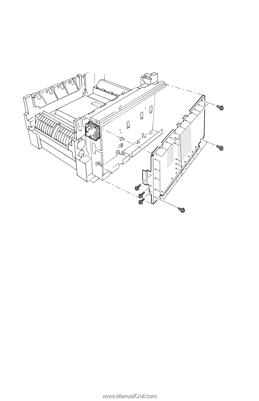
| Rear Shield Plate (PL 3.1) |
162 |
| 1. Remove the Rear Cover (see pg. 6-135). |
162 |
| 2. Remove 34 G screws securing the Rear Shield Plate. |
162 |
| 3. Remove the Rear Shield Plate. |
162 |
| Electrical Card Cage (PL 3.10) and Electrical Cage Fan (PL 3.9) |
163 |
| Fan Removal |
163 |
| 1. Remove the Rear Cover (see pg. 6-135). |
163 |
| 2. Remove the Rear Shield Plate (see pg. 6-146). |
163 |
| 3. Disconnect the fan harness from the Engine Controller Board. |
163 |
| 4. Remove 2 screws and the spacers securing the fan to the Electrical Card Cage. |
163 |
| 5. Remove the Electrical Cage Fan. |
163 |
| Card Cage Removal |
163 |
| 1. Remove the Image Processor Board (see pg. 6-142). |
163 |
| 2. Remove the Rear Shield Plate (see pg. 6-146). |
163 |
| 3. Remove 4 G and 4 B screws securing the Top Shield Plate (item #1) to the electrical card cage.... |
163 |
| 4. Disconnect all connectors and ribbon cables from the print engine controller board. |
163 |
| 5. Pull out disconnected cable harnesses routed through the top of the Printer Unit Chassis. |
163 |
| 6. Remove disconnected cable harnesses from the card cage. |
163 |
| 7. Remove the 3 G and 1 B screws securing the EMI shield (covering the ribbon cables) from the to... |
164 |
| 8. Remove the 5 screws securing the print Engine Controller Board. |
164 |
| 9. Remove the Engine Controller Board (see pg. 6-149). |
164 |
| 10. Remove the harnesses from the front of the electrical card cage. |
164 |
| 11. Remove the 13 G screws securing the electrical card cage to the printer frame. |
164 |
| 12. Guide the bottom harnesses as you carefully remove the electrical card cage. |
164 |
| Print Engine Controller Board (PL 3.8) |
165 |
| 1. Remove the Image Processor Board (see pg. 6-142). |
165 |
| 2. Remove the Rear Cover (see pg. 6-135) |
165 |
| 3. Remove the Rear Shield Plate (see pg. 6-146). |
165 |
| Wiring |
165 |
| 4. Disconnect all connectors to the Engine Controller Board. Remove EMI suppressor coils and cabl... |
165 |
| 5. Remove 5 screws securing the Engine Controller Board to the Electrical Card Cage. |
165 |
| 6. Remove the Engine Controller Board. |
165 |
| Top Cover Inner Frame (PL 4.16) Front Damper (PL 1.8), Rear Damper (PL 1.11), Top Cover Hinge Spr... |
166 |
| 1. Remove the Top Cover (see pg. 6-133). |
166 |
| 2. Remove the Left-side Cover (see pg. 6-138). |
166 |
| 3. Remove the Front Cover (see pg. 6-136). |
166 |
| 4. Remove the Front Shield Plate, 5 G screws and 3 B screws. |
166 |
| 5. Remove the Rear Shield Plate (see pg. 6-146). |
166 |
| 6. Remove the 4 G and 4 B screws securing the Top Shield Plate to the Electrical Card Cage and re... |
167 |
| 7. Remove 5 screws securing the Top Cover Rear Damper (item #1). Tilt the top cover forward sligh... |
167 |
| 8. Disconnect all 9 LED flat wiring harnesses from the Engine Controller Board. |
167 |
| 9. Remove 4 screws securing the cable shield to the top of the Electrical Card Cage. Free the fla... |
167 |
| 10. Disconnect the 4 top-cover (inner frame) wiring harness interconnects located next to the rea... |
167 |
| 11. Remove the 5 screws securing the Top Cover Front Damper (item #6). Tilt the Top Cover forward... |
167 |
| 12. Supporting the weight of the Top Cover Inner Frame, gently lower the inner frame into its clo... |
167 |
| 13. Carefully slide the Top Cover Hinge Shaft (item #2) toward the rear of the printer to free it... |
167 |
| 14. Remove the Top Cover Inner Frame. (item # 4). |
167 |
| Reassembly |
167 |
| Toner Sensor Board (PL 4.19) |
168 |
| 1. Remove the Top Cover (see pg. 6-133). |
168 |
| 2. From the underside of the Top Cover Inner Frame, disconnect the 4 LED power harnesses from the... |
168 |
| 3. Close the Top Cover Inner Frame. |
168 |
| 4. Remove 3 B screws securing the Toner Sensor Board. |
168 |
| 5. Rotate the board to expose the underside of the board. |
168 |
| 6. Disconnect the 7 harnesses from the Toner Sensor Board. |
168 |
| 7. Remove the Toner Sensor Board. |
168 |
| Toner Cartridge Sensor Actuators (PL 4.18) |
169 |
| 1. Remove the Toner Sensor Board (item #3) and LED Harnesses (item #2) (see pg. 6-152). |
169 |
| 2. Rotate the board up to expose the component side of the board. |
169 |
| 3. From the underside of the Top Cover Inner Frame, use a small screwdriver to carefully push up ... |
169 |
| 4. Remove the Toner Cartridge Sensor Actuator (item #1). |
169 |
| Duplex Unit Assembly (PL 1.15) |
170 |
| 1. Pull out the Duplex Unit and Tray 1 together. |
170 |
| 2. On the right side locate the release lever (next to the guide pin) and pull forward to release... |
170 |
| 3. Holding tray 1, force the duplex unit backwards about 5 cm and lift the duplex unit to separat... |
170 |
| Reassembly |
170 |
| 1. Align the guide pins carefully then push down on the guide pins to lock the Duplex unit in pla... |
170 |
| Front Chassis Fan (PL 5.2.4) |
171 |
| 1. Remove the Front Cover (see pg. 6-136). |
171 |
| 2. Remove the Duplex Unit and Tray 1 (see pg. 6-154). |
171 |
| 3. Remove the Front Shield Plate, 5 G screws and 3 B screws. |
171 |
| 4. Disconnect the Front Power Supply Fan’s wiring harness (item #1) from the Low Voltage Power Su... |
171 |
| 5. Remove 2 B screws securing the fan and slide the Front Power Supply Fan out of the printer frame. |
171 |
| Printer Unit Chassis (PL 5.1.14) |
172 |
| 1. Remove the Fuser and the Transfer Unit. |
172 |
| 2. Remove the Image Processor Board (see pg. 6-142). |
172 |
| 3. Remove the Rear Cover (see pg. 6-135). |
172 |
| 4. Remove the Front Cover (see pg. 6-136). |
172 |
| 5. Remove the Left Side Cover (see pg. 6-138). |
172 |
| 6. Remove the 5 G and 2 B screws securing the Left Side Shield Plate and remove the plate. |
172 |
| 7. Remove the 5 G screws and the 3 B screw securing the Front Shield Plate and remove. |
172 |
| 8. Remove the Multi-Purpose Tray (see pg. 6-140). |
172 |
| 9. Remove the 4 G and 4 B screws securing the Top Shield Plate to the Electrical Card Cage and re... |
172 |
| 10. Disconnect the LED ribbon connectors located at the upper right corner of the Engine Controll... |
172 |
| 11. Remove all the screws securing the EMI shield (covering the ribbon cables) from the top of th... |
172 |
| 12. Pull the disconnected ribbon cables through the top of the electrical card cage. Tape the ope... |
172 |
| 13. Disconnect the following top cover intermediate power connectors and clear them from the fan ... |
173 |
| 14. Disconnect the serial port wiring harness at the left-rear of the Printer Unit Chassis. |
173 |
| 15. Remove the Side Output Tray Sensor Harness and pull it through the chassis. |
173 |
| 16. Disconnect the wiring harness from the Registration Motor. |
173 |
| 17. Disconnect and label the following connectors from the Engine Controller Board: |
175 |
| 18. Disconnect the following at the front of the printer: |
175 |
| 19. Remove 1 screw securing the AC power switch (item #1) to the printer frame. |
175 |
| 20. Free the power switch from the Printer Unit Chassis and let it hang. |
175 |
| 21. Remove 12 screws securing the Printer Unit Chassis to the frame, 4 GB screws 4�G and 4 B screws. |
176 |
| 22. Lift each corner carefully to make certain the chassis is free. |
177 |
| 23. Elevate the Printer Unit Chassis from the printer frame and place a ream of paper or large sc... |
177 |
| 24. Carefully lift the chassis straight up from the printer frame. Rest the chassis upside-down o... |
177 |
| Replacement |
177 |
| 1. Reverse these steps to install the printer unit chassis. Ensure the front shield plate rests b... |
177 |
| Rear Power Supply Fan (PL 5.1.31) |
178 |
| 1. Remove the Printer Unit Chassis (see pg. 6-156). |
178 |
| 2. Remove 1 screw securing the fan to the fan duct. |
178 |
| 3. Slide the Rear Power Supply Fan out of the duct, 2 screws secure the duct in place |
178 |
| Entrance Sensor Board (PL 5.1.17) |
179 |
| 1. Remove the Multi-Purpose Tray (see pg. 6-140). |
179 |
| 2. Remove the Printer Unit Chassis (see pg. 6-156). |
179 |
| 3. Turn the chassis upside-down and remove the Registration Roller B Assembly (see pg. 6-178). |
179 |
| 4. Remove the spring loaded Registration Entrance Sensor Actuator (see pg. 6-170). |
179 |
| 5. Remove 2 B screws securing the Entrance Sensor Board. |
179 |
| 6. Remove the board and disconnect the wiring harness from FSNS. |
179 |
| Front Plate Assembly (PL 5.2.3) |
180 |
| 1. Remove the Printer Unit Chassis (see pg. 6-156). |
180 |
| 2. Remove 2 screws from the Front Power Supply Fan. Let the fan rest on the front of the lower pl... |
180 |
| 3. Disconnect the Front Chassis Fan from the front of the low-voltage power supply board (item�#1). |
180 |
| 4. Remove 4 G screws securing the Front Plate Assembly (item #2) to the lower plate (item #3) and... |
180 |
| High Voltage Power Supply (PL 5.2.9) |
181 |
| 1. Remove the Printer Unit Chassis (see pg. 6-156). |
181 |
| 2. Disconnect CN1 from the High Voltage Power Supply. |
181 |
| 3. Disconnect CN3 from the Low Voltage Power Supply. |
181 |
| 4. Remove 3 screws securing the High Voltage Power Supply to the chassis. |
181 |
| 5. Lift the High Voltage Power Supply and the contact assembly from the Printer Unit Chassis to r... |
181 |
| 6. Remove the contact assembly from the High Voltage Power Supply. |
181 |
| Low Voltage Power Supply (PL 5.2.12) |
182 |
| 1. Remove the Printer Unit Chassis (see pg. 6-156). |
182 |
| 2. Unplug connectors CN1, CN2, CN3 and AC-IN from the Low Voltage Power Supply. |
182 |
| 3. Disconnect the AC power switch wiring harness interconnect. |
182 |
| 4. Remove the 8 B screws securing the Low Voltage Power Supply to the printer. |
182 |
| 5. Remove the Low Voltage Power Supply. |
182 |
| Tray 1 Pick and Feed Rollers (PL 6.1.2) (set of 3 interchangeable rollers), Torque Limiter (PL 6.... |
183 |
| 1. Remove Tray 1. |
183 |
| 2. Reach into the cavity and release the locking tab on the front end of the feed rollers. |
183 |
| 3. Slide the feed rollers to the front to remove them. |
183 |
| 4. Release the locking tab on the front end of the nudger roller. |
183 |
| 5. Slide the nudger roller to the front and remove. |
183 |
| 1 Bearing, One-Way Feed Roller |
183 |
| 2 Nudge Roller |
183 |
| 3 Locking Tab |
183 |
| 4 Feed Rollers |
183 |
| 5 Torque Limiter |
183 |
| Paper Size Sensor Board (PL 6.1.1) |
184 |
| 1. Remove Tray 1. |
184 |
| 2. Reach in through the printer cavity left by tray 1 and disconnect the ribbon cable attached to... |
184 |
| 3. Remove the 4 G screws securing the Paper Size Sensor Board to the printer. |
184 |
| 4. Remove the Paper Size Sensor Board. |
184 |
| Main Feeder Assembly (PL 6.1.6) |
185 |
| 1. Remove Tray 1. |
185 |
| 2. Remove the Rear Cover (see pg. 6-135). |
185 |
| 3. Remove the Right Cover (Door A) (see pg. 6-139). |
185 |
| 4. Disconnect the 8 wiring connectors leading to the Main Feeder Assembly. There are 5 intermedia... |
185 |
| 5. Remove the main feeder cross brace; it is held in place with 5 screws. |
185 |
| 6. Remove the 4 G screws around the outer edge of the Main Feeder Assembly. |
185 |
| 7. On the right side of the printer, remove the 2 G screws from the front of the assembly. |
185 |
| 8. Reach into the printer cavity left by Tray 1 and remove the 2 screws securing the Main Feeder ... |
185 |
| Registration Entrance Sensor Actuator (B) (PL 5.1.15) |
186 |
| 1. Remove the Printer Unit Chassis (see pg. 6-156). |
186 |
| 2. Turn the Printer Unit Chassis upside-down and carefully squeeze the actuator’s two locking tab... |
186 |
| Transfer Belt Entrance Sensor Actuator (PL 5.1.18) MPT Entrance Sensor Actuator (PL 5.1.19) |
187 |
| 1. Remove the Printer Unit Chassis (see pg. 6-156). |
187 |
| 2. Remove the Registration Entrance Sensor Actuator (see pg. 6-170). |
187 |
| 3. Remove the Entrance Sensor Board (see pg. 6-163). |
187 |
| 4. From the bottom, squeeze the two locking tabs securing the MPT Entrance Sensor Actuator (item ... |
187 |
| 5. From the bottom, squeeze the two locking tabs securing the Transfer Belt Entrance Sensor Actua... |
187 |
| Top/Side Output Solenoid (PL 5.1.6) and Duplex Gate Solenoid (PL 5.1.8) |
188 |
| 1. Remove the Front Cover (see pg. 6-136). |
188 |
| 2. Remove the Front Shield Plate. |
188 |
| 3. Free the Front Power Supply Fan and let it hang. |
188 |
| 4. Disconnect the wiring harness from the Top/Side Output Solenoid (item #1). |
188 |
| 5. Disconnect the wiring harness from the Duplex Gate Solenoid (item #2). |
188 |
| 6. Remove 2 B screws securing the each solenoid and remove from the Printer Unit Chassis. |
188 |
| Registration Clutch (PL 5.1.20) |
189 |
| 1. Remove the Rear Shield Plate (see pg. 6-146). |
189 |
| 2. Disconnect the RCL connector from the Engine Controller Board. |
189 |
| 3. Remove 1 screw securing the ground strap to the motor bracket. |
189 |
| 4. Remove the e-ring (item #1) securing the clutch to the registration shaft B. |
189 |
| 5. Remove the Registration Clutch (item #2). |
189 |
| Reassembly |
189 |
| Registration Motor Assembly (PL 5.1.21) |
190 |
| 1. Remove the Rear Cover (see pg. 6-135). |
190 |
| 2. Remove the Rear Shield Plate (see pg. 6-146). |
190 |
| 3. Remove the Registration Clutch (see pg. 6-173). |
190 |
| 4. Remove 1 small G and 3 B screws securing the motor to the bracket (item #1). |
190 |
| 5. Disconnect the harness to the Registration Motor Assembly. |
190 |
| 6. Remove the Registration Motor Assembly (item #2). |
190 |
| Auto Thickness Sensor (ATS) - Pickup Cover Assembly (PL 5.1.25) and Pickup Plate Assembly (PL 5.1... |
191 |
| 1. Remove the Front Cover (see pg. 6-136) |
191 |
| 2. Remove the Rear Cover (see pg. 6-135) |
191 |
| 3. Remove the MPT Pick Assembly (see pg. 6-140) |
191 |
| 4. Remove the Pickup Cover Assembly from the Pickup Plate Assembly. |
191 |
| 5. Disconnect the wiring harness from the sensor. |
191 |
| 6. Remove 2 screws securing the Pickup Plate Assembly and remove. |
191 |
| 7. Remove the ATS sensor. |
191 |
| ATS Anvil (not spared, part of Registration Roller A) |
192 |
| 1. Remove the Registration Roller (A) Assembly (see pg. 6-177) |
192 |
| 2. Remove 1 screw securing the Anvil and remove the Anvil. |
192 |
| Registration Roller Assembly A (PL 5.1.22) and Drive Gear (PL 5.1.26) |
193 |
| 1. Remove the Transfer Unit. |
193 |
| 2. Remove the Rear Shield Plate (see pg. 6-146). |
193 |
| 3. Remove the MPT Pick Assembly (see pg. 6-140). |
193 |
| 4. Remove the ATS Anvil (see pg. 6-176). |
193 |
| 5. Remove the 4 B screws securing the Registration Roller Assembly A. |
193 |
| 6. Lift the roller assembly and remove. |
193 |
| 7. Remove the E-ring securing the drive gear to the back end of the Registration Roller Assembly. |
193 |
| 8. Remove the Drive Gear. |
193 |
| Registration Roller Assembly B (PL 5.1.16) |
194 |
| 1. Remove the Printer Unit Chassis (see pg. 6-156). |
194 |
| 2. Turn the Printer Unit Chassis upside-down and remove the 4 B screws securing Registration Roll... |
194 |
| 3. Lift the roller up and toward the front of the printer and remove. |
194 |
| Duplex Guide Assembly (PL 5.1.2) |
195 |
| 1. Grasp the Duplex Guide Assembly and pull the assembly straight up and out of the printer. |
195 |
| Fuser Latching Handle (Front) (PL 5.1.4) |
196 |
| 1. Remove the Front Cover (see pg. 6-136). |
196 |
| 2. Remove the Fuser. |
196 |
| 3. Release the fuser latching handle spring (item #2). |
196 |
| 4. Remove 2 B screws securing the Fuser Latching Handle (item #1) to the Printer Unit Chassis and... |
196 |
| Fuser Latching Handle (Rear) (PL 5.2.1) |
197 |
| 1. Remove the Printer Unit Chassis (see pg. 6-156). |
197 |
| 2. Release the fuser latching handle spring (item #3). |
197 |
| 3. Remove the e-ring (item #2) securing the Rear Fuser Latching Handle to its shaft. |
197 |
| 4. Slide the rear Fuser Latching Handle (item #1) off the shaft to remove. |
197 |
| Fuser Exit Roller (PL 5.1.1) |
198 |
| 1. Remove the Front Cover (see pg. 6-136). |
198 |
| 2. Remove the Rear Shield Plate (see pg. 6-146). |
198 |
| 3. Remove the Rear Power Supply Fan and Duct (see pg. 6-162). |
198 |
| 4. Remove the Front Chassis Fan (see pg. 6-155). |
198 |
| 5. Remove the Electrical Card Cage (see pg. 6-147). |
198 |
| 6. Lift and remove the Duplex Guide Assembly (see pg. 6-179). |
198 |
| 7. At the rear of the Fuser Exit Roller (item #2), remove 1 G screw securing the ground contact (... |
198 |
| 8. Remove the bearing, 1 B screw, and the fuser drive gear. |
198 |
| 9. At the front of the Fuser Exit Roller, release the two locking tabs and remove the bearing (it... |
198 |
| 10. Slide the Fuser Exit Roller to the rear of the printer until the front end of the shaft is fr... |
198 |
| Fuser Exit Sensor Assembly (PL 5.1.3) |
199 |
| 1. Remove the Fuser Exit Roller (see pg. 6-182). |
199 |
| 2. Remove the Print Unit Chassis (see pg. 6-156). |
199 |
| 3. From the Engine Controller Board, remove the connector to the Fuser Exit Sensor Assembly (PART... |
199 |
| 4. Lift and remove the Duplex Exit Gate. |
199 |
| 5. Remove 1 B screw securing the Fuser Exit Sensor Assembly. |
199 |
| 6. Guide the sensor wiring harness through the chassis as you remove the assembly. |
199 |
| Eject Guide Assembly (PL 4.8) |
200 |
| 1. Remove the Top Cover Inner Frame (see pg. 6-150). |
200 |
| 2. Remove 7 B screws securing the Eject Guide Assembly to the Top Cover Inner Frame. |
200 |
| 3. Remove the assembly. |
200 |
| Stack Full Sensor (PL 4.5) and Actuator (PL 4.4) |
201 |
| 1. Remove the Top Cover (see pg. 6-133). |
201 |
| 2. Disconnect the cable from the Stack Full Sensor. |
201 |
| 3. Release the 4 locking tabs securing the Stack Full Sensor (item #2), and remove the sensor and... |
201 |
| Back Plate Assembly w/Drive Gears (PL 5.2.11) and Imaging Unit Motors (PL 5.2.13) |
202 |
| 1. Remove the Printer Unit Chassis (see pg. 6-156). |
202 |
| 2. Remove the 5 G screws securing the Back Plate Assembly to the frame. |
202 |
| 3. Disconnect the wiring harnesses from all four Imaging Unit Motors. |
202 |
| 4. Lift the front of the Back Plate Assembly about 2 cm (3/4 in.) and carefully guide the ribbon ... |
202 |
| Imaging Unit Motors |
202 |
| 1. Remove 2 G screws securing the Imaging Unit Motor to the Back Plate Assembly. |
202 |
| 2. Disconnect cable. |
202 |
| 3. Remove the motor. |
202 |
| Transfer Unit Motor Assembly (PL 5.2.2) (contains Fuser Motor) |
203 |
| 1. Remove the Print Unit Chassis (see pg. 6-156). |
203 |
| 2. Remove 2 G screws securing the Fuser Motor and Transfer Unit Motor Assembly to the chassis and... |
203 |
| 3. Disconnect the two in-line connectors (item #2) leading to the Fuser Motor and Transfer Unit M... |
203 |
| Color Registration Plate Shutter (PL 5.1.11) |
204 |
| 1. Carefully remove the shutter spring through the opening in the plate shutter. |
204 |
| 2. Open the shutter plate to the full open position. |
204 |
| 3. Carefully lift the tabs on the right end of the shutter over the stopper and continue to move ... |
204 |
| 4. Remove the shutter. |
204 |
| Reassembly |
204 |
| Color Registration Sensor Assembly (PL 5.1.10) |
205 |
| 1. Remove the Color Registration Plate Shutter (see pg. 6-188). |
205 |
| 2. Remove 2 B screws securing the Color Registration Sensor Assembly. |
205 |
| 3. As you lift the assembly, carefully disconnect the 3 harnesses connected to the assembly. |
205 |
| Reassembly |
205 |
| Color Registration Shutter Solenoid (PL 5.1.13) |
206 |
| 1. Remove the Printer Unit Chassis (see pg. 6-156). |
206 |
| 2. Remove the Color Registration Plate Shutter (see pg. 6-188). |
206 |
| 3. Disconnect the Color Registration Shutter Solenoid’s in-line connector. |
206 |
| 4. Release the solenoid harness (item #2) from all cable clamps. |
206 |
| 5. Remove the screw securing the solenoid (item #1) to the Printer Unit Chassis to remove the sol... |
206 |
| LED Head 600 dpi (PL 4.9a) and LED Head Holder (PL 4.9b) |
207 |
| 1. Disconnect the LED Head y power harness from the Toner Sensor Board. |
207 |
| 2. Carefully disconnect both cables (item C) from the LED Head. Note the cable routing for reasse... |
207 |
| 3. With small screwdriver, carefully release the LED Head from the LED Head Holder. |
207 |
| (Imaging Unit) Drum Contact Assembly (PL 5.1.27) |
208 |
| 1. Use a small screwdriver to carefully pry the Drum Contact Assembly from the Printer Unit Chassis. |
208 |
| Field Replaceable Units (FRU) Parts List |
209 |
| Using the parts list |
209 |
| Contents |
209 |
| PL 1.0 - Covers |
210 |
| 1 |
211 |
| 2 |
211 |
| 3 |
211 |
| 4 |
211 |
| 5 |
211 |
| 6 |
211 |
| 7 |
211 |
| 8 |
211 |
| 9 |
211 |
| 10 |
211 |
| 11 |
211 |
| 12 |
211 |
| 13 |
211 |
| 14 |
211 |
| 15 |
211 |
| 16 |
211 |
| 17 |
211 |
| 18 |
211 |
| 19 |
211 |
| 20 |
211 |
| 21 |
211 |
| 22 |
211 |
| 23 |
211 |
| 24 |
211 |
| PL 2.0 - MPT Pick Assembly |
212 |
| 1 |
213 |
| 2 |
213 |
| 3 |
213 |
| 4 |
213 |
| 5 |
213 |
| 6 |
213 |
| 7 |
213 |
| 8 |
213 |
| 9 |
213 |
| PL 3.0 - Printer Control Components Boards |
214 |
| 1 |
215 |
| 2 |
215 |
| 3 |
215 |
| 4 |
215 |
| 5 |
215 |
| 6 |
215 |
| 7 |
215 |
| 8 |
215 |
| 9 |
215 |
| 10 |
215 |
| 11 |
215 |
| PL 4.0 - Top Cover Inner Frame |
216 |
| 1 |
217 |
| 2 |
217 |
| 3 |
217 |
| 4 |
217 |
| 5 |
217 |
| 6 |
217 |
| 7 |
217 |
| 8 |
217 |
| 9 a 9b |
217 |
| 10 |
217 |
| 11 |
217 |
| 12 |
217 |
| 13 |
217 |
| 14 |
217 |
| 15 |
217 |
| 16 |
217 |
| 17 |
217 |
| 18 |
217 |
| 19 |
217 |
| PL 5.1 - Printer Unit Chassis (1 of 2) |
218 |
| 1 |
219 |
| 2 |
219 |
| 3 |
219 |
| 4 |
219 |
| 5 |
219 |
| 6 |
219 |
| 7 |
219 |
| 8 |
219 |
| 9 |
219 |
| 10 |
219 |
| 11 |
219 |
| 12 |
219 |
| 13 |
219 |
| 14 |
219 |
| 15 |
219 |
| 16 |
219 |
| 17 |
219 |
| 18 |
219 |
| 19 |
219 |
| 20 |
219 |
| 21 |
219 |
| 22 |
219 |
| 23 |
219 |
| 24 |
219 |
| 25 |
219 |
| 26 |
219 |
| 27 |
219 |
| 28 |
219 |
| 29 |
219 |
| 30 |
219 |
| 31 |
219 |
| PL 5.2 - Printer Unit Chassis (2 of 2) and Power Supplies |
220 |
| 1 |
221 |
| 2 |
221 |
| 3 |
221 |
| 4 |
221 |
| 5 |
221 |
| 6 |
221 |
| 7 |
221 |
| 8 |
221 |
| 9 |
221 |
| 10 |
221 |
| 11 |
221 |
| 12 |
221 |
| 13 |
221 |
| PL 6.1 - Paper Tray 1 |
222 |
| 1 |
223 |
| 2 |
223 |
| 3 |
223 |
| 4 |
223 |
| 5 |
223 |
| 6 |
223 |
| 7 |
223 |
| 8 |
223 |
| 9 |
223 |
| 10 |
223 |
| PL 6.2 - Lower Tray Deck & Lower Tray Assembly (Trays 2, 3, 4, 5) |
224 |
| 1 |
225 |
| 2 |
225 |
| 3 |
225 |
| 4 |
225 |
| 5 |
225 |
| 6 |
225 |
| 7 |
225 |
| 8 |
225 |
| 9 |
225 |
| Kits |
226 |
| Hardware Kit |
226 |
| Gear kit |
226 |
| Harness kit |
227 |
| LED Harness Kit |
227 |
| Flag Kit |
228 |
| Supplies and Accessories |
229 |
| Toner Vacuum and Accessories |
229 |
| Packaging |
229 |
| Manuals and CD’s |
229 |
| Customer Replaceable Consumables |
230 |
| 1 |
230 |
| 2 |
230 |
| 3 |
230 |
| Paper and Media |
231 |
| Theory of Operation |
235 |
| Contents |
235 |
| Mechanical Process of the Printer |
236 |
| Summary of the Printing Process |
237 |
| 1. Paper Pick and Transport - For the entire paper path, see page 8 - 226. |
237 |
| 2. Charging - DC voltage applies a negative charge to the charge roller and the surface of the im... |
237 |
| 3. Exposure - The LED head emits light to the negatively charged surface of the drum. Areas of th... |
237 |
| 4. Developing and recovery of excessive toner - Toner is attracted to the electrostatic image on ... |
237 |
| 5. Transfer - The transfer roller applies a positive charge to the back side of the paper. The to... |
237 |
| 6. Cleaning - A cleaning blade, located on the transfer unit, scrapes off excess toner left on th... |
237 |
| 7. Fusing - The fuser permanently fixes the toner image to the paper using a combination of heat ... |
237 |
| Charging |
238 |
| Exposure |
238 |
| Developing |
238 |
| 1. The sponge roller transfers toner to the developing roller. The toner is negatively charged. |
238 |
| 2. The toner cleaning blade scrapes away excessive toner on the developing roller to form a thin ... |
239 |
| 3. The toner is attracted to the latent image on the surface of the drum at the point where the d... |
239 |
| Transfer |
239 |
| Fusing |
240 |
| Imaging Unit Cleaning |
241 |
| Transfer Unit Cleaning |
241 |
| Summary of the Paper Path |
242 |
| Paper Fed from Tray 1 |
243 |
| 1. The feed motor, rotating in the direction shown, drives the pick and feed rollers, feeding a s... |
243 |
| 2. After the leading edge of the paper comes in contact with the registration entrance sensor, th... |
243 |
| 3. The registration motor, rotating in the direction shown, synchronizes with the paper feed oper... |
243 |
| 4. At this time the feed motor stops rotating. The rollers free-wheel as the remainder of the she... |
243 |
| 5. The registration motor moves the paper until the trailing edge passes the transfer belt entran... |
243 |
| Paper Fed from Optional Trays |
244 |
| Paper Fed from the Multi-Purpose Tray |
245 |
| 1. The hopper-plate is pushed down by the release lever to signalling the MPT roller home positio... |
245 |
| 2. The registration motor rotates in the direction shown, driving the MPT feed roller causing the... |
245 |
| 3. After the transfer belt entrance sensor senses the leading edge of the paper, the paper is tra... |
245 |
| 4. Concurrently, the cam pushes down the hopper plate, which is locked by the spring-loaded relea... |
245 |
| 5. After completing the paper feed operation, the registration motor rotates to drive the registr... |
245 |
| Transfer Unit |
246 |
| Imaging Unit Up/Down Movement |
247 |
| 1. Rotation and up/down operation of the imaging unit are conducted by a single pulse motor. The ... |
247 |
| 2. Rotating the imaging unit main motor in the direction of the arrow (b) causes lever 1 to push ... |
247 |
| 3. The imaging drum contacts sense “on” when two pins are pushed up by the springs on the board t... |
247 |
| Transfer Unit Arm and Gear Up/Down Movement of the Imaging Units |
248 |
| Fuser and Paper Exit |
249 |
| 1. The fuser motor drives the fuser unit and eject rollers. As the fuser motor rotates counter-cl... |
249 |
| 2. At the same time, the four sets of eject rollers rotate to eject the print. |
249 |
| 3. The eject route to the left side output tray is selected by a spring-loaded separator gate. Wi... |
249 |
| Duplex Unit |
250 |
| 1. When the duplex unit receives instructions from the printer to print on both sides of a sheet ... |
250 |
| 2. When the leading edge of the paper passes through the duplex entrance sensor, the rollers reve... |
250 |
| Paper Jam Detection |
251 |
| Paper Size Sensing |
252 |
| 1. Paper Size Sensor Board |
252 |
| 2. Plate on the back of the Paper Tray |
252 |
| Fuser Temperature Settings |
253 |
| Cover Open Detection |
254 |
| Toner Detection |
255 |
| Toner Full State |
255 |
| Toner Low State |
256 |
| Color Registration Detection |
257 |
| Customer Replaceable Consumable Detection |
258 |
| Customer Replaceable Consumable (CRC) Life Counter Behavior |
258 |
| Printer Components |
260 |
| 1. Front Panel - The front panel provides the user interface to the printer. |
260 |
| 2. Image Processor Board - The image processor board converts the data from the print jobs into b... |
260 |
| 3. Engine Controller Board - The engine controller board synchronizes the print process by contro... |
261 |
| 4. Toner Sensor Board - |
261 |
| 5. Low Voltage Power Supply |
261 |
| 6. High Voltage Power Supply |
261 |
| 7. Entrance Sensor Board - contains the following sensors: |
261 |
| 8. Paper Size Sensor Board - The position of a multi-slotted plate, at the rear of the paper tray... |
261 |
| 9. Imaging Unit Sensor Board |
261 |
| Engine Controller Board Connectors |
262 |
| Engine Controller Board Connectors (cont'd.) |
262 |
| Sensors |
264 |
| Sensor Location and Function |
265 |
| 1. |
265 |
| 2. |
265 |
| 3. |
265 |
| 4. |
265 |
| 5. |
265 |
| 6. |
265 |
| 7. |
265 |
| 8. |
265 |
| 9. |
265 |
| 10. |
265 |
| 11. |
265 |
| 12. |
265 |
| 13. |
265 |
| 14. |
265 |
| 15. |
265 |
| 16. |
265 |
| 17. |
265 |
| 18. |
265 |
| 19. |
265 |
| 20. |
265 |
| 21. |
265 |
| Clutches, Motors and Solenoids |
266 |
| 1 |
266 |
| 2 |
266 |
| 3 |
266 |
| 4 |
266 |
| 5 |
266 |
| 6 |
266 |
| 7 |
266 |
| 8 |
266 |
| 9 |
266 |
| 10 |
266 |
| 11 |
266 |
| 12 |
266 |
| 13 |
266 |
| 14 |
266 |
| Wiring Diagrams |
267 |
 1
1 157
157 158
158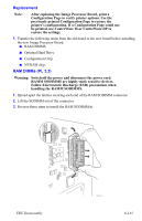 159
159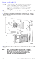 160
160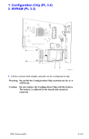 161
161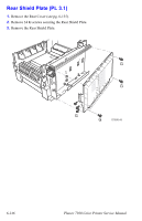 162
162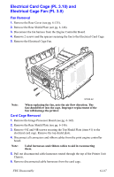 163
163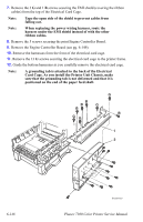 164
164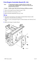 165
165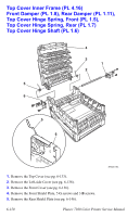 166
166 167
167