Yamaha AX-9 Owner's Manual - Page 6
CONNECTIONS, Never plug in this unit and other components until all connections are completed.
 |
View all Yamaha AX-9 manuals
Add to My Manuals
Save this manual to your list of manuals |
Page 6 highlights
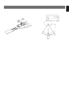
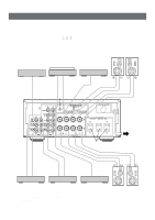
CONNECTIONS Never plug in this unit and other components until all connections are completed. q When making connections between this unit and other components, be sure all connections are made correctly, that is to say L (left) to L, R (right) to R, "+" to "+" and "-" to "-". Also, refer to the owner's manual for each component to be connected to this unit. q If you have YAMAHA components numbered as 1, 2, 3, etc. on the rear panel, connections can be made easily by making sure to connect the output (or input) terminals of each component to the same-numbered terminals of this unit. Tuner Turntable Right Speakers A Left CD player LINE OUT OUTPUT GND LINE OUT R L PHONO R 2 TUNER 3 or 5 TAPE PB 1 CD L AUX 3 PLAY 4 or 6 4 RECOUT REC R L R L TAPE MD AUDIO SIGNAL 2 * GND IMPEDANCE SELECTOR SET BEFORE POWER ON VOLTAGE SELECTOR A OR B:4ΩMIN./SPEAKER A + B:8ΩMIN./SPEAKER A OR B:8ΩMIN./SPEAKER A + B:l6ΩMIN./SPEAKER AC OUTLETS A SWITCHED l00W MAX. TOTAL +R B L SPEAKERS + 1 * (General model) To AC outlet LINE OUT LINE IN LINE OUT LINE IN AUDIO OUT Tape deck, etc. MD recorder, etc. * *1 , 2 : Refer to "ABOUT THE ACCESSORY TERMINALS" on page 7. 6 Right Video cassette player, LD player, etc. Left Speakers B
-
 1
1 -
 2
2 -
 3
3 -
 4
4 -
 5
5 -
 6
6 -
 7
7 -
 8
8 -
 9
9 -
 10
10 -
 11
11 -
 12
12 -
13
-
14
-
15
 |
 |
