Yamaha DM1000 Studio Manager Owner's Manual - Page 12
Output Channels, When the Master Layer is selected
 |
View all Yamaha DM1000 manuals
Add to My Manuals
Save this manual to your list of manuals |
Page 12 highlights
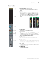
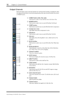
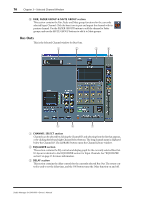
12 Chapter 2-Console Window Output Channels When the Master Layer is selected, the Bus Out and Aux Send channels are displayed. A Bus Out channel is shown here. Aux Send channels appear the same except that they do not have a STEREO button. A STEREO button (Bus Out only) This button is used to route the Bus Out to the Stereo Out. B INSERT button This button is used to turn on and off the Bus Out's Insert. 1 C COMP button This button is used to turn on and off the Bus Out's Compressor. 2 D Compressor curve This display shows the Compressor's curve. E EQ button C This button is used to turn on and off the Bus Out's EQ. D F EQ curve 5 This display shows the Equalizer's curve, which can be set by 6 dragging. 7 8 I G DELAY button This button is used to turn on and off the Bus Out's Delay func- tion. H Delay parameter This parameter is used to set the delay time of the Delay function. Delay times can be set by dragging. I Channel number This is the channel number. J AUTO button J This button displays the Automix status of the Bus Out. K L K SELECT button M This button is used to select the Bus Out. N L SOLO button This button solos the Bus Out. It appears orange while the Bus O Out is soloed. M ON button This button turns the Bus Out on and off. It appears orange while the Bus Out is on. P N Short channel name This is the channel's short name. To edit the name, click it and type. O Channel fader This is the Bus Out's fader. P Channel meter This meter displays the signal level of the Bus Out. Studio Manager for DM1000-Owner's Manual
-
 1
1 -
2
-
3
-
4
-
5
-
6
-
 7
7 -
 8
8 -
 9
9 -
 10
10 -
 11
11 -
 12
12 -
 13
13 -
 14
14 -
 15
15 -
 16
16 -
 17
17 -
18
-
19
-
20
-
21
-
22
-
23
-
24
-
25
-
26
-
27
-
28
-
29
-
30
-
31
-
32
-
33
-
34
 |
 |
