Yamaha DTX720K DTX582K/DTX720K Assembly Manual - Page 2
Connect the drum trigger module to a power supply.
 |
View all Yamaha DTX720K manuals
Add to My Manuals
Save this manual to your list of manuals |
Page 2 highlights
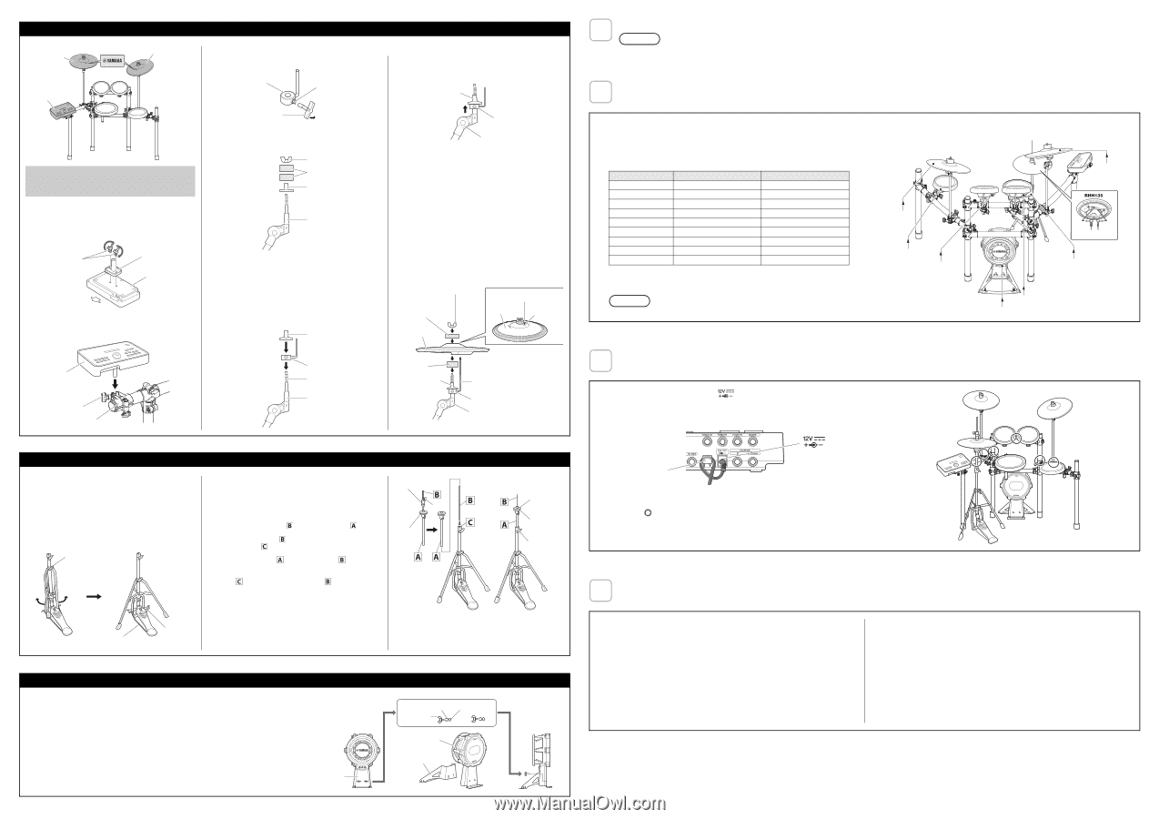
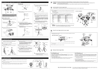
Assembling the drum trigger module and cymbal pads PCY135 PCY135 Cymbal pads 1. Using the tuning key, loosen the stopper's key bolt. Drum trigger module Stopper Key bolt Tuning key A cymbal pad's built-in sensor is located close to the Yamaha logo found on the top surface. In order to achieve the best performance from your pad, position it such that the area around the logo can be easily struck. (See the figure above.) Drum trigger module 1. Secure the module holder to the bottom of the drum trigger module using the module holder screws. 2. Remove the wing nut, the two felt pads, and the bolt cover from the cymbal holder. Wing nut Felt pads Bolt cover Cymbal holder Module holder screws * Two screws for DTX502 / Four screws for DTX700 Module holder Drum trigger module (rear side) Front side 2. Push the module holder into the holder clamp and tighten the clamp bolt to secure it in place. 3. Place the stopper on the cymbal holder. * If the key bolt was not sufficiently loosened in Step 1 above, it may not be possible to pass the stopper over the cymbal holder's shaft. In such a case, loosen the key bolt as much as possible without removing it. 4. Replace the bolt cover. * Turn the bolt cover to tighten it onto the threaded section and firmly secure it in place. Bolt cover 5. With the stopper making full contact with the bottom surface of the bolt cover as shown below, tighten the stopper's key bolt using the tuning key. Bolt cover Full contact Stopper Cymbal holder 6. Place one of the felt pads removed in Step 2 on the cymbal holder. 7. Mount the pad on the cymbal stand. Lower the pad into place with the cymbal holder's shaft passing through the central hole. When mounted, the stopper's pin should rest inside the pad's smaller hole. * If you were to play your cymbal pad without the stopper's pin positioned well inside the smaller hole, the pad could rotate, causing the pin to be pulled out. It is very important, therefore, to ensure that the stopper is secured as shown in Step 5 above. 8. Assemble the felt pad that came with the cymbal pad. * The second felt pad removed from the cymbal holder in Step 2 above is not required for assembly. 9. Tighten the wing nut to secure the pad to the cymbal holder. Wing nut Felt pad that came with cymbal Stopper's pin Cymbal pad Smaller hole Cymbal pad 4 Arrange the hi-hat stand and the kick pad as shown in Example of standard assembly on the other side of this sheet. NOTICE • Lay a drum mat (sold separately) on the floor underneath the hi-hat stand and the kick pad. Alternatively, you can place cardboard from the drum kit packaging or the like on the floor to prevent it from being scratched. • Ensure that you do not lower the electronic drum rack's center strut too much as doing so may cause it to come into contact with the kick pad. 5 Connect the pads to the drum trigger module. As described below, connect the output of each pad to the corresponding trigger input jack on the drum trigger module. 1. Plug the straight ends of the nine-channel snake cable into the trigger input jacks on the back of the drum trigger module. • When using the standard setup, the stickers on each of the snake cable's plugs will indicate the name of the corresponding pad. 2. Plug the L-shaped ends of the nine-channel snake cable into the corresponding pads. Pads SNARE TOM1 TOM2 TOM3 RIDE CRASH KICK HI HAT HH CON DTX502 jack names q SNARE w TOM1/!0 e TOM2/!1 r TOM3/!2 t RIDE y CRASH u KICK/i o HI HAT HI-HAT CONTROL DTX700 jack names q SNARE w TOM1 e TOM2 r TOM3 t RIDE y CRASH1 o KICK/!0 i HI HAT HI-HAT CONTROL 3. In the case of snare and tom pads, wrap the cables around the cable clips to prevent them from being pulled out. NOTICE Excessive bending can damage pad cables. Ensure, therefore, that these cables are not bent at an extreme angle when wrapped around the clips. Locations of pad jacks RIDE TOM3 TOM2 TOM1 KICK CRASH HI HAT HH CON SNARE Drum trigger module + module holder Insert Clamp bolt Holder clamp Stopper Threaded section Cymbal holder Assembling the hi-hat stand 1. If a drum mat (sold separately) is not available, lay a sheet of cardboard on the floor to protect it from being scratched. 2. Loosen the hi-hat stand's wing bolt a. 3. Open up the three legs as shown below and then retighten the wing bolt a to lock them in place. 4. Insert the footboard stabilizer rods into the frame holes as shown below. Wing bolt a Footboard stabilizer rod Footboard stabilizer rod 5. As shown on the right, loosen the hi-hat clutch's wing bolt b and remove the hi-hat clutch. * The hi-hat clutch is not required when assembling the electronic drum kit in the standard fashion described in this manual. Instead, the hi-hat clutch that came with the RHH135 Real Hi-Hat Pad will be used. 6. Remove the hi-hat shaft from the upper tube . 7. Insert the hi-hat shaft from Step 6 as far as it will go into the lower tube and screw in the tip. 8. Insert the upper tube over the hi-hat shaft and tighten the wing bolt c to secure it in place with the cymbal support plate approximately half way between the top of the lower tube and the top of the hi-hat shaft . 9. Remove the felt pad attached above the cymbal support plate. It is not required when assembling the electronic drum kit in the standard fashion described in this manual. Assembling the kick pad 1. If a drum mat (sold separately) is not available, lay a sheet of cardboard on the floor to protect it from being scratched. 2. Remove the two wing bolts, spring washers, and flat washers from the kick pad frame, and line up each set nearby in the order of removal. 3. Join the base section to the frame as shown on the right, and then secure it in place by assembling the wing bolts, spring washers, and flat washers removed in the previous step from the base side. Frame Felt pad Bolt cover Pin Stopper Cymbal holder Hi-hat clutch b Cymbal support plate Felt washer Cymbal support plate c 6 Connect the drum trigger module to a power supply. 1. Plug the power adaptor's DC cord into the the cord clip to secure it in place. Drum trigger module's rear panel connector. Hook the power adaptor's DC cord around connector Cord clip * The illustration shows the DTX502 drum trigger module. 2. Using the cable bands, secure the cables to the electronic drum rack at the positions circled in the figure on the right. ( ) 3. Plug the adaptor's AC cord into a domestic wall socket. 7 Setting up the drum trigger module. 10. Assemble the RHH135 Real Hi-hat Pad. * For detailed instructions, refer to the Setting Up section in the RHH135 Owner's Manual. Spring washer Flat washer Wing bolt Frame Base [For DTX582K Owners] Select the "DTX582K" trigger setup on the DTX502 drum trigger module. (For details on the trigger setup procedure, see "Trigger Setup" from the DTX502 Owner's Manual.) If "DTX582K" is not displayed on the selection screen, select the "DTX562K" trigger setup, and then make the following adjustment. • Kick pad output (LEVEL) adjustment: Adjust the trigger output to your desired setting by using the KP100 kick pad's level adjustment knob. For details, see "Adjusting the Output Level" from the KP100 Owner's Manual. [For DTX720K Owners] Select the "DTX720K" trigger setup on the DTX700 drum trigger module. (For details on the trigger setup procedure, see "Selecting a Sensitivity for the Entire Kit" from the DTX700 Owner's Manual.) If "DTX720K" is not displayed on the selection screen, please upgrade your DTX700's firmware version. Visit the following web page for information on the latest DTX700 firmware version and to download firmware version upgrades. http://download.yamaha.com/ If you would prefer not to upgrade your firmware version, select the "DTX700K" trigger setup, and then make the following adjustment. • Kick pad output (LEVEL) adjustment: Adjust the trigger output to your desired setting by using the KP100 kick pad's level adjustment knob. For details, see "Adjusting the Output Level" from the KP100 Owner's Manual. Your electronic drum kit is now ready. * For instructions on turning on the drum trigger module, producing sounds, and other subsequent steps, please refer to the Owner's Manual that came with the module. 2
-
 1
1 -
 2
2
 |
 |