Yamaha DTX8K-X DTX8K-X DTX8K-M Assembly Manual - Page 2
Connect the pads to the drum trigger module.
 |
View all Yamaha DTX8K-X manuals
Add to My Manuals
Save this manual to your list of manuals |
Page 2 highlights
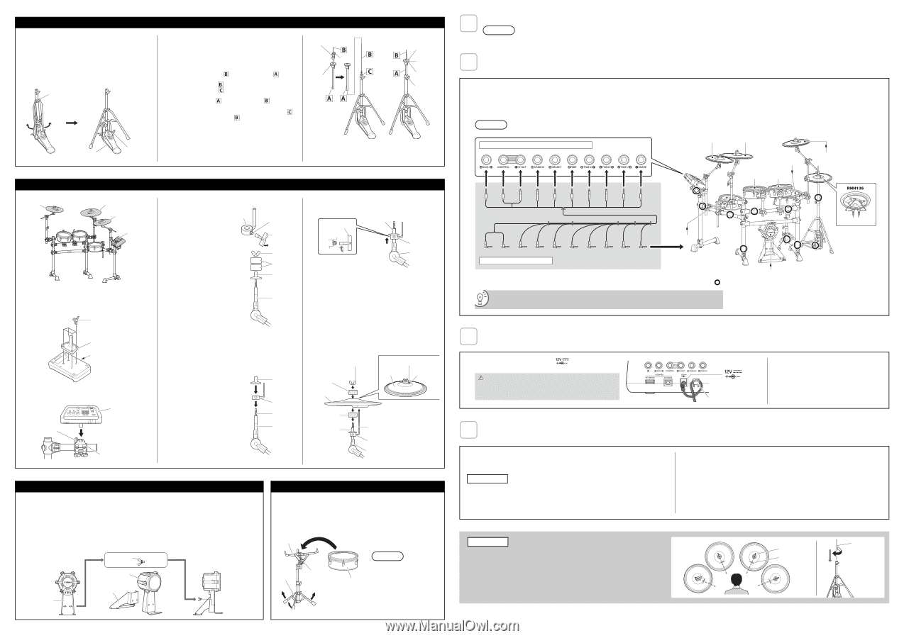
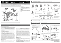
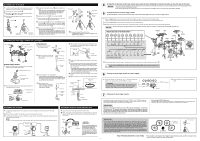
Assembling the hi-hat stand 1. If a drum mat (sold separately) is not available, lay a sheet of cardboard on the floor to prevent it from being scratched. 2. Loosen the hi-hat stand's wing bolt a. 3. Open up the three legs as shown below and then retighten the wing bolt a to lock them in place. 4. Insert the footboard stabilizer rods into the frame holes as shown below. Wing bolt a Footboard stabilizer rod Footboard stabilizer rod 5. Loosen the hi-hat clutch's wing bolt b and remove the hi-hat clutch. * The hi-hat clutch is not required when assembling the electronic drum kit in the standard fashion described in this manual. Instead, the hi-hat clutch that came with the RHH135 Real Hi-hat Pad will be used. 6. Remove the hi-hat shaft from the upper tube . 7. Insert the hi-hat shaft go into the lower tube removed in Step 6 as far as it will and screw in the tip. 8. Insert the upper tube over the hi-hat shaft and tighten the wing bolt c to secure it in place with the cymbal support approximately half way between the top of the lower tube and the top of the hi-hat shaft . 9. Remove the felt washer attached above the cymbal support. * Do not remove the Metal washer. * The felt washer is not used when assembling the electronic drum kit in the standard fashion described in this manual. If you leave it on, you will not be able to get the proper playing feeling, so be sure to remove it. Hi-hat clutch b Cymbal support Felt washer Metal washer Cymbal support c 10. Assemble the RHH135 Real Hi-hat Pad. * For detailed instructions, refer to the "Setting Up" in the RHH135 Owner's Manual. Assembling the drum trigger module and cymbal pads PCY135 cymbal pad PCY155 cymbal pad PCY135 cymbal pad Drum trigger module Cymbal pads 1. Using the drum key, loosen the stopper's key bolt. Stopper 2. Remove the wing nut, the two felt pads, and the bolt cover from the cymbal holder. Key bolt Drum key Wing nut Felt pads Bolt cover Drum trigger module 1. Secure the module holder to the bottom of the drum trigger module using the module holder screws. Module holder screw (×4) Cymbal holder Module holder Drum trigger module (rear side) 2. Push the module holder into the holder clamp and tighten the clamp bolt to secure it in place. Drum trigger module + module holder Clamp bolt Insert 3. Place the stopper on the cymbal holder. * If the key bolt was not sufficiently loosened in Step 1 above, the cymbal holder may not pass through the hole of the stopper. In such a case, loosen the key bolt as much as possible without removing it. 4. Replace the bolt cover. * Turn the bolt cover to tighten it onto the threaded section and firmly secure it in place. Bolt cover Stopper Threaded section Cymbal holder Holder clamp 5. With the stopper making full contact with the bottom surface of the bolt cover as shown below, tighten the stopper's key bolt using the drum key. Drum key Bolt cover Full contact Stopper Cymbal holder 6. Place one of the felt pads removed in Step 2 on the cymbal holder. 7. Mount the pad on the cymbal stand. Lower the pad into place with the cymbal holder's shaft passing through the central hole. When mounted, the stopper's pin should rest inside the pad's smaller hole. * Playing your pad unit without the stopper's pin positioned fully inside the smaller hole could cause slip out of the hole. It is very important, therefore, to ensure that the stopper is secured as shown in Step 5 above. 8. Assemble the other felt pad removed in Step 2 to the cymbal holder. 9. Tighten the wing nut to secure the pad to the cymbal holder. Wing nut Felt pad removed in Step 2 Cymbal pad Stopper's pin Cymbal pad Smaller hole Felt pad removed in Step 2 Bolt cover Pin Stopper Cymbal holder Assembling the kick pad 1. If a drum mat (sold separately) is not available, lay a sheet of cardboard on the floor to prevent it from being scratched. 2. Remove the two wing bolts from the kick pad frame, and then place them nearby. 3. Join the base to the frame as shown on the below, and then secure it in place by the wing bolts removed in the pre- vious step from the base side. NOTE For details on assembling the foot pedal (sold separately), refer to the "Assembling the KP90" in the KP90 Owner's Manual. Wing bolt Frame Frame Base Assembling the Snare Stand and Snare Pad 1. Open up the snare stand's legs and stand it up on the floor. 2. Open up the snare stand's basket section, lay the Snare Pad on it, adjust the basket, and then tighten the adjusting knob to secure the pad and prevent it from moving. Basket Legs Adjusting knob XP125SD NOTICE Before every playing, tighten the drum key bolts so that there is no rattling and loosening of the head, in order to prevent malfunction. Refer to the "Head tension adjustment" in the XP105TX XP105T-M XP125T-X XP125T-M XP125SD-X XP125SD-M Owner's Manual. 2 4 Arrange the hi-hat stand, the kick pad, and the snare stand as shown in Example of standard assembly on the other side of this sheet. NOTICE • Lay a drum mat (sold separately) on the floor underneath the hi-hat stand and the kick pad. Alternatively, you can place cardboard from the drum kit packaging or the like on the floor to prevent it from being scratched. • Ensure that you do not lower the electronic drum rack's center strut too much as doing so may cause it to come into contact with the kick pad. 5 Connect the pads to the drum trigger module. As described below, connect the output of each pad to the corresponding trigger input jack on the drum trigger module. 1. Plug the straight ends of the ten-channel snake cable into the trigger input jacks on the back of the drum trigger module. • When using the standard setup, the stickers on each of the snake cable's plugs will indicate the name of the corresponding pad. 2. Plug the L-shaped ends of the ten-channel snake cable into the corresponding pads. 3. Wrap the cables for the snare pad, the tom pads, the cymbal pads and the hi-hat pad around the cable clips to prevent them from being pulled out. NOTICE Excessive bending can damage pad cables. Ensure, therefore, that these cables are not bent at an extreme angle when wrapped around the clips. Trigger input jacks on the drum module CRASH2 RIDE SNARE TOM2 TOM1 CRASH KICK HH CON HI HAT CRASH2 CRASH RIDE TOM3 TOM2 TOM1 SNARE HH CON HI HAT SNARE CRASH TOM1 RIDE KICK TOM2 TOM3 CRASH2 Ten-channel snake cable TOM3 4. Using the cable bands, secure the cables to the electronic drum rack at the positions circled in the figure on the right. ( ) If you secure the cable band from the side closer to the drum trigger module, you can make connections more easily. KICK HI HAT HH CON 6 Connect the drum trigger module to a power supply. 1. Plug the AC adaptor's DC cord into the connector. Hook the AC adaptor's DC cord around the cord clip to secure it in place. CAUTION Excessive bending can damage AC adaptor's DC cord. Ensure, therefore, that the cord is not bent at an extreme angle when wrapped around the clips. Doing so can cause fire or electrical shock. connector 2. Plug the adaptor's AC cord into a domestic wall socket. Cord clip 7 Setting up the drum trigger module. According to your particular electronic drum kit, select the "DTX8K-X" or the "DTX8K-M" trigger setup on your drum trigger module. (For details on the trigger setup procedure, refer to the "Initial Settings (Trigger Setup Wizard)" in the DTX-PRO Owner's Manual.) IMPORTANT The letters at the end of the model name ("X" or "M") indicates the pad type. "X" represents TCS products and "M" represents mesh products. Selecting the wrong trigger setup will adversely affect your ability to perform comfortably, since sensing when the drum is hit differs depending on the pad type. Use the correct trigger setup that corresponds to your particular electronic drum kit for optimum performance. • Kick pad output (LEVEL) adjustment: Adjust the trigger output to your desired setting by using the KP90 kick pad's level adjustment knob. For details, refer to the "Adjusting the Output Level" in the KP90 Owner's Manual. IMPORTANT • You can play comfortably by striking near the YAMAHA logo. Adjust the height, angle and orientation of the cymbal pad and hi-hat pad to a position where you can hit around the YAMAHA logo naturally when performing. The correct setting position is that the YAMAHA logo of the cymbal pad and hi-hat pad are visible in front of the performer. The direction of the cymbal pad will be appropriate by adjusting the direction of the stopper as shown on the right. The direction of the hi-hat pad will also be appropriate by adjusting the direction of the hi-hat clutch. • The hi-hat shaft will become loose while you continue to use the hi-hat, and the hi-hat pad may rotate. Since this may adversely affect performance, screw in the hi-hat shaft periodically and adjust the position of the hi-hat pad. Stopper's pin YAMAHA logo Hi-hat shaft Screw in Your electronic drum kit is now ready. * For instructions on turning on the drum trigger module, producing sounds, and other subsequent steps, refer to the Owner's Manual that came with the module.
-
 1
1 -
 2
2
 |
 |