Yamaha DV-S5950 Owners Manual - Page 9
Functional Overview
 |
View all Yamaha DV-S5950 manuals
Add to My Manuals
Save this manual to your list of manuals |
Page 9 highlights
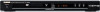
English Front panel Functional Overview HDMI 1 2 345 6 789 1 STANDBY/ON Turns on this unit or sets it to the standby mode. 2 Disc tray Loads a disc in the disc tray. 3 OPEN/CLOSE (/) Opens or closes the disc tray. 4 HDMI indicator Lights up when an HDMI component is connected, and signals output via the HDMI jack of this unit. 5 PROGRESSIVE indicator Lights up when this unit enters the progressive mode. 6 Front panel display Shows the current status of this unit. 7 PLAY (B) Starts playback. 8 PAUSE (;) Pauses playback. 9 STOP (9) Stops playback. Rear panel HDMI 1 2 3 4 567 1 AC power cord Connect to a standard AC outlet. 2 HDMI output jack Connect to the HDMI input jack of your HDMI component. 3 AUDIO OUT (L, R) jacks Connect to the audio input jacks of your AV receiver or stereo system. 4 DIGITAL OUT - COAXIAL jack Connect to the coaxial input jack of your AV receiver. 5 VIDEO OUT - COMPONENT (Y, PB, PR jacks Connect to the component input jacks of your AV receiver. 6 VIDEO OUT - S VIDEO jack Connect to the S-video input jack of your AV receiver. 7 VIDEO OUT - VIDEO jack Connect to the composite video input jack of your AV receiver. Caution: Do not touch the inner pins of the jacks on the rear panel of this unit. Electrostatic discharge may cause permanent damage to this unit. Downloaded from www.Manualslib.com manuals search engine 5 En
-
 1
1 -
2
-
3
-
 4
4 -
 5
5 -
 6
6 -
 7
7 -
 8
8 -
 9
9 -
 10
10 -
 11
11 -
 12
12 -
 13
13 -
 14
14 -
15
-
16
-
17
-
18
-
19
-
20
-
21
-
22
-
23
-
24
-
25
-
26
-
27
-
28
-
29
-
30
-
31
-
32
-
33
-
34
-
35
-
36
-
37
-
38
-
39
-
40
-
41
-
42
-
43
-
44
-
45
-
46
-
47
 |
 |
