Yamaha IVN Owner's Manual - Page 5
Connection Example 2 - rights
 |
View all Yamaha IVN manuals
Add to My Manuals
Save this manual to your list of manuals |
Page 5 highlights
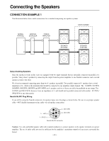
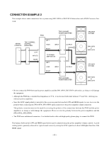
CONNECTION EXAMPLE 2 This example shows audio connections for a system using SW118IVN or SW215IVN Subwoofers and a PN90 Crossover Network. MIXING CONSOLE L R PN90 TWO-CHANNEL POWER AMPLIFIER TWO-CHANNEL GRAPHIC EQUALIZER LEFT HIGH LL INPUT OUTPUT L LEFT INPUTS RIGHT R RIGHT TO POWER AMP INPUTS LEFT RR LL LOW INPUT OUTPUT RIGHT RR TWO-CHANNEL POWER AMPLIFIER SPEAKER SYSTEM SW118IVN or SW215IVN SPEAKER SYSTEM SW118IVN or SW215IVN • Do not connect the PN90 between the power amplifiers and the SW118IVN, SW215IVN subwoofers, as doing so will damage the equipment. • Although the PN90 has a standard load impedance of 15 k , it can be used with loads between 7.5 and 30 k , allowing use with most power amplifiers. • Since the LOW signal polarity is inverted at the crossover point between the LOW and HIGH signals, be sure to reverse the polarity when connecting the SW118IVN, SW215IVN input connectors to the power amplifier output connectors. This polarity correction must not be made by reversing the polarity of the connections between the PN90 and the power amplifiers, as doing so will damage the equipment. Please reverse the polarity between the power amplifiers and the SW118IVNs, SW215IVNs. • The PN90 uses unbalanced connectors. Use shielded audio cable with high-quality phone plugs to connect the PN90. The balance between the LOW and HIGH signal levels may be adjusted using the power amplifier volume controls. A good starting point is generally achieved for typical sound sources by raising the LOW signal level about 8 dB higher than that of the HIGH signal. - 5 -
-
 1
1 -
 2
2 -
 3
3 -
 4
4 -
 5
5 -
 6
6 -
 7
7 -
 8
8 -
 9
9 -
 10
10
 |
 |
