Yamaha MSR400 Owner's Manual - Page 5
Rear Panel - used
 |
UPC - 086792831343
View all Yamaha MSR400 manuals
Add to My Manuals
Save this manual to your list of manuals |
Page 5 highlights
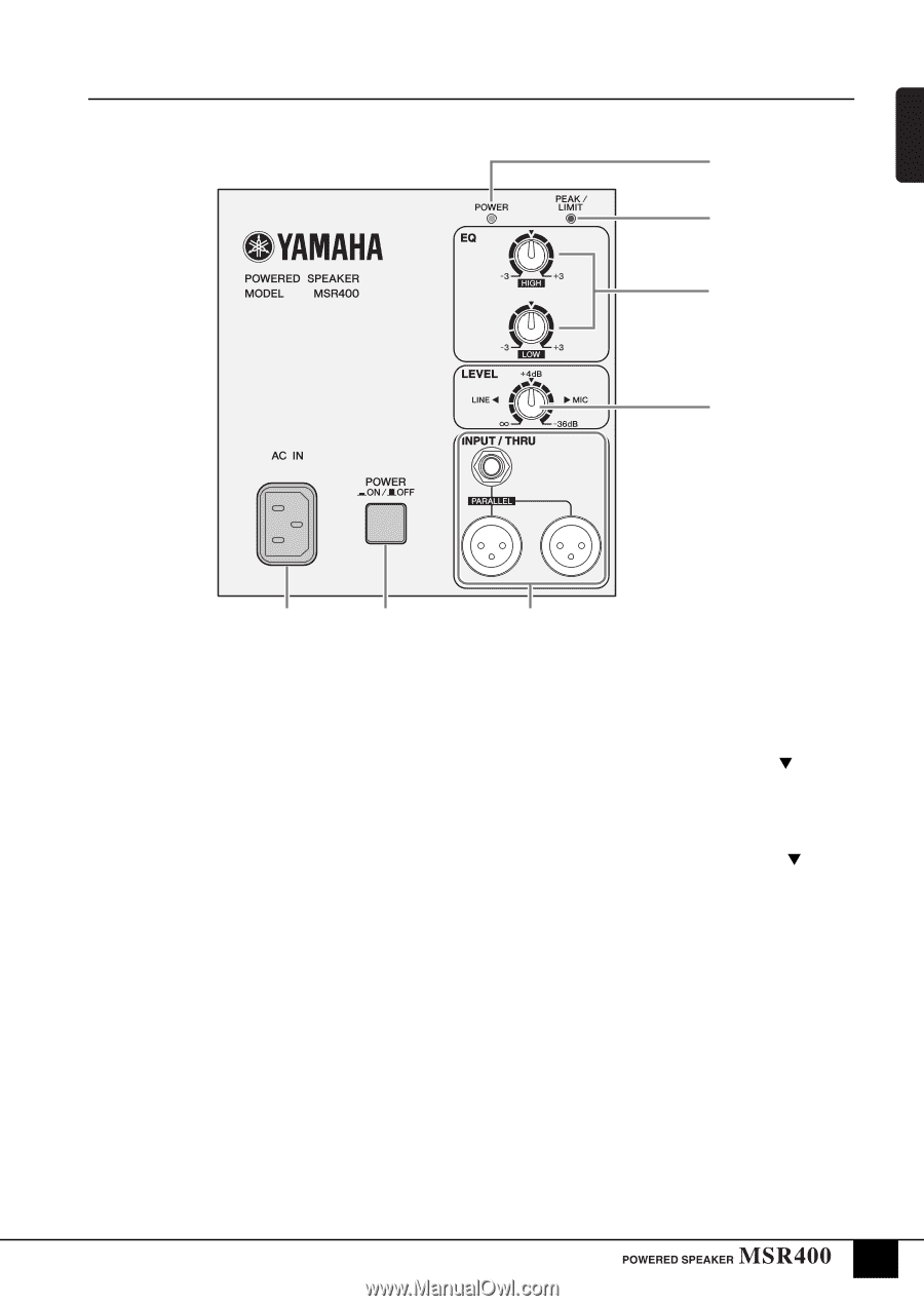
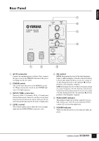
ENGLISH Rear Panel 7 6 5 4 2 1 3 1 2 3 1 2 3 1 AC IN connector Connect the included power cord here. First, connect the power cord to the MSR400, then insert the power cord plug into the AC outlet. 2 POWER switch This switch turns the power to the MSR400 on and off. When you turn this switch on, the POWER indi- cator (7) lights up green. 3 INPUT/THRU connectors These are XLR-3-31 (female), XLR-3-32 (male) and balanced phone jack connectors, and they accept input from mic-level to line-level sources. They are all connected in parallel and can also be used as output jacks. 4 LEVEL control This control enables you to adjust the level of signal input from the INPUT/THRU connectors (3). 5 EQ control HIGH: Determines the level of the high frequency band (1.6 kHz and higher). Turn the control clockwise to boost and counterclockwise to cut over a range of ±3 dB. Setting the knob to the optimum position produces a flat frequency response. LOW: Determines the level of the low frequency band at a center frequency of 55 Hz. Turn the control clockwise to boost and counterclockwise to cut over a range of ±3 dB. Setting the knob to the optimum position produces a flat frequency response. 6 PEAK/LIMIT indicator This indicator lights up red if the output level is too high. In this case, lower the level using the LEVEL control (4) or lower the input level. 7 POWER indicator When you turn the power on, this indicator lights up green. 5
-
 1
1 -
 2
2 -
 3
3 -
 4
4 -
 5
5 -
 6
6 -
 7
7 -
 8
8 -
 9
9 -
 10
10 -
 11
11
 |
 |