Yamaha MSR800W Owner's Manual - Page 5
Rear panel - msr400 &
 |
UPC - 086792831350
View all Yamaha MSR800W manuals
Add to My Manuals
Save this manual to your list of manuals |
Page 5 highlights
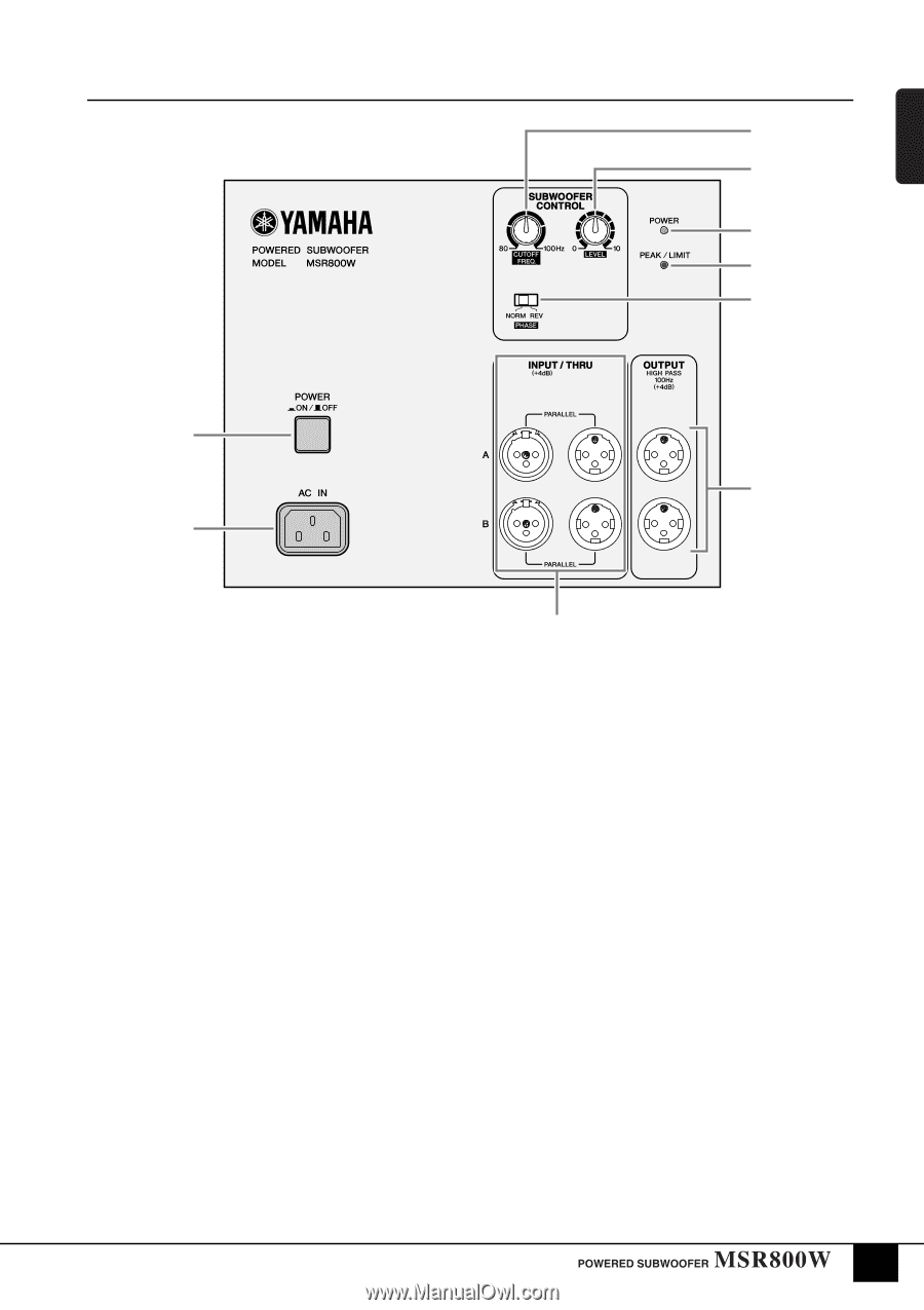
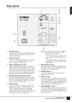
ENGLISH Rear panel 9 8 7 6 5 1 4 2 1 POWER switch This switch turns the power to the MSR800W on and off. When this switch is turned on, the green power indicator (7) lights up. 2 AC IN connector Connect the included power cord here. First, connect the power cord to the MSR800W, then insert the power cord plug into the AC outlet. 3 INPUT/THRU jacks A and B These are XLR-type balanced jacks. Two different signals can be input at these INPUT jacks. If two signals are input at the same time, they are mixed before being sent to the subwoofer. They are connected in parallel for A and B signals independently, and either one of the jacks can also be used as an output jack. 4 OUTPUT HIGH PASS jacks A and B These are XLR-type balanced output jacks. Connect these jacks to the main speakers to cut the range below 100 Hz of signals input from INPUT jacks A and B and route them to the main speakers. 5 PHASE switch This switch enables you to select a phase. You will usually set this switch to "NORM". However, the "REV" setting may improve low-range sounds, depending on the type and location of the entire speaker system. Try both settings and select the one with a better-sounding low-range output. 3 NOTE: If you connect the output jacks to the MSR400 powered speaker, we recommend to set this PHASE switch (5) as follows: - Set the PHASE switch (5) to "REV" when the signal is output from the INPUT/THRU A, B jacks. - Set the PHASE switch (5) to "NORM" when the signal is output from the OUTPUT HIGH PASS A, B jacks. 6 PEAK/LIMIT indicator This indicator lights up red if the output level is too high. In this case, lower the level using the LEVEL control (8) or lower the input level. 7 POWER indicator This indicator lights up green when you turn the POWER switch (1) ON. 8 LEVEL control This control enables you to adjust the sound volume level. The maximum level is at the scale setting of 10, and the minimum level is at the scale setting of 0. If the level is too high, the PEAK/LIMIT indicator (6) lights up red. In this case, lower the level. 9 CUTOFF FREQ. control This control enables you to adjust the cutoff frequency in the range of 80 through 100 Hz depending on the speakers you are using with the MSR800W and your personal preferences. 5
-
 1
1 -
 2
2 -
 3
3 -
 4
4 -
 5
5 -
 6
6 -
 7
7 -
 8
8 -
 9
9 -
 10
10 -
 11
11
 |
 |