Yamaha NS-P220 Owner's Manual - Page 14
USING THE SUBWOOFER (SW-P201), Controls and their functions
 |
View all Yamaha NS-P220 manuals
Add to My Manuals
Save this manual to your list of manuals |
Page 14 highlights
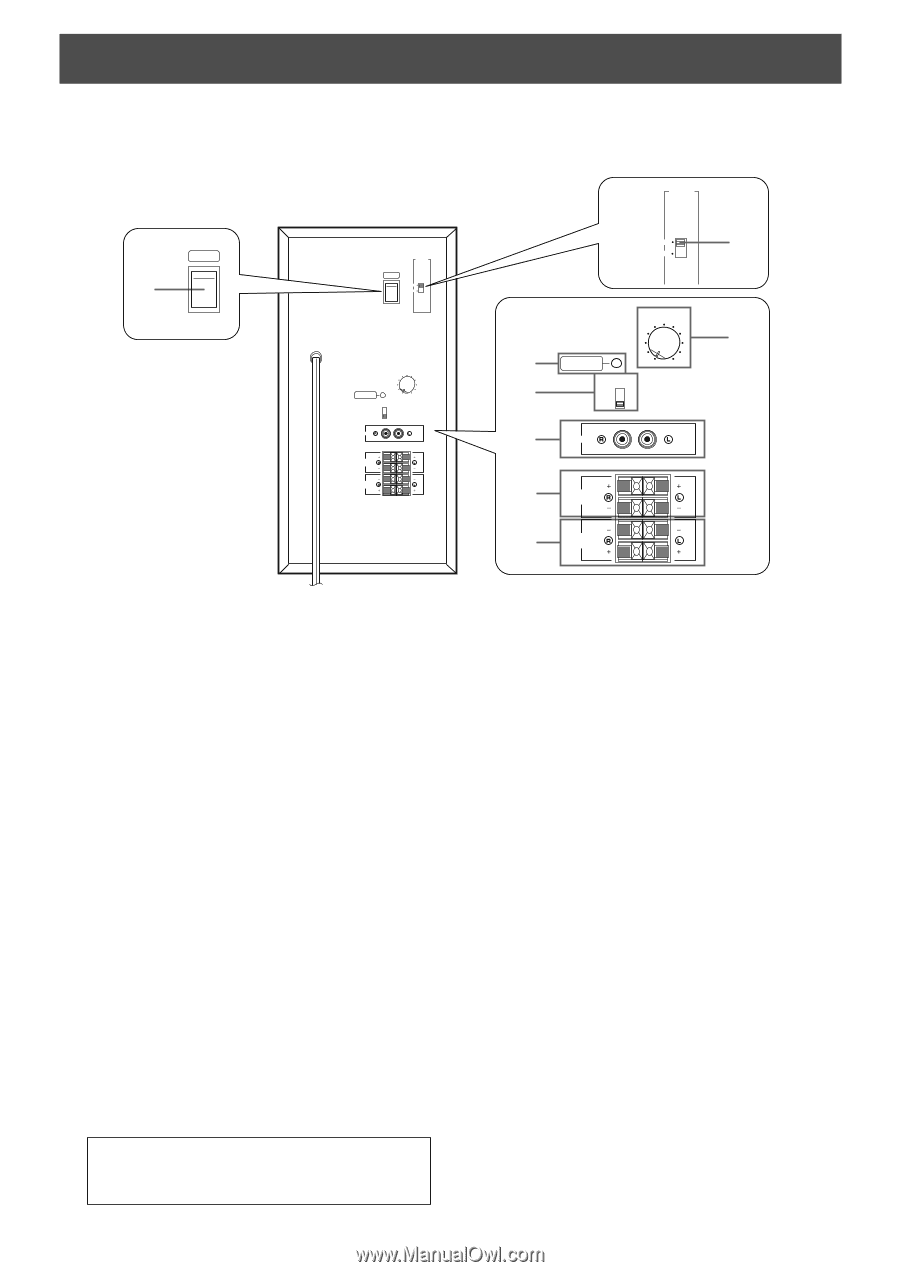
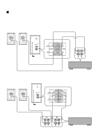
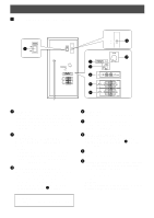
USING THE SUBWOOFER (SW-P201) Ⅵ Controls and their functions POWER 1 ON OFF Rear panel VOLTAGE SELECTOR POWER ON OFF 220V-240V 110V-120V VOLUME STANDBY-RED ON-GREEN AUTO STANDBY HIGH LOW OFF 0 I0 INPUT2 /MONO INPUT1 FROM AMPLIFIER OUTPUT TO SPEAKERS VOLTAGE SELECTOR 220V-240V 110V-120V 8 VOLUME 2 3 4 STANDBY-RED ON-GREEN AUTO STANDBY HIGH LOW OFF 0 I0 INPUT2 /MONO 7 5 INPUT1 FROM AMPLIFIER 6 OUTPUT TO SPEAKERS 1 POWER switch Set this switch to the ON position to turn on the power of the subwoofer. When the power of the subwoofer is on, the power indicator below the POWER switch lights up GREEN. Set this switch to the OFF position to turn off the power of the subwoofer. 2 Power indicator Lights up GREEN when the POWER switch is set to the ON position and goes off when set to the OFF position. * Standby mode If the POWER switch is set to the ON position and the AUTO STANDBY switch is set to the HIGH or LOW position, this indicator lights up RED when no signal is inputted to the subwoofer. 3 AUTO STANDBY (HIGH/LOW/OFF) switch By setting this switch to the HIGH or LOW position, the subwoofer's automatic power-switching function operates as described on the next page. If you do not need this function, set to the OFF position. * Make sure to change the setting of this switch only when the POWER switch (1) is in the OFF position. Standby mode The subwoofer is still using a small amount of power in this mode. 10 4 INPUT2 terminals Used to input line level signals from the amplifier. 5 INPUT1 (FROM AMPLIFIER) terminals Used to connect the subwoofer with the speaker terminals of the amplifier. 6 OUTPUT (TO SPEAKERS) terminals Can be used for connecting to the main speakers. Signals from the INPUT1 terminals (5) are sent to these terminals. 7 VOLUME control Adjusts the volume level. 8 VOLTAGE SELECTOR switch (General model only) If the preset setting of the switch is incorrect, set the switch to the proper voltage range (220V-240V or 110V-120V) of your area. Consult your dealer if you are unsure of the correct setting. WARNING Be sure to unplug the subwoofer before setting the VOLTAGE SELECTOR switch correctly.
-
 1
1 -
2
-
3
-
4
-
5
-
6
-
7
-
8
-
 9
9 -
 10
10 -
 11
11 -
 12
12 -
 13
13 -
 14
14 -
 15
15 -
 16
16 -
 17
17 -
 18
18 -
 19
19
 |
 |