Yamaha RX-V540 Owner's Manual - Page 21
PREPARATION, SUBWOOFER jack, MAIN SPEAKERS terminals, Notes - remote control
 |
View all Yamaha RX-V540 manuals
Add to My Manuals
Save this manual to your list of manuals |
Page 21 highlights
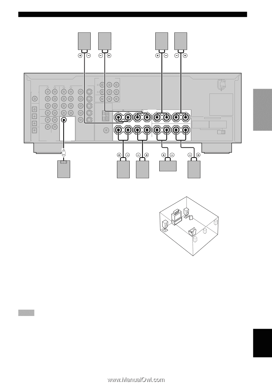
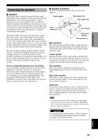
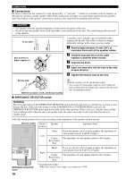
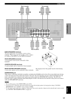
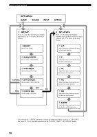
Main A speaker Right Left 1 2 Rear speaker Right Left 3 4 CONNECTIONS PREPARATION AUDIO R L DIGITAL CD INPUT CD 5 COAXIAL 4 OPTICAL D-TV/CBL IN (PLAY) MD /CD-R OUT (REC) 3 DVD MAIN AUDIO R L VIDEO VIDEO S VIDEO DVD COMPORNENT VIDEO PR PB Y DVD A D-TV /CBL B D-TV /CBL MONITOR OUT TUNER IN VCR R OUT AM ANT 2 MD/CD-R SURROUND GND 1 MD/CD-R OPTICAL DIGITAL OUTPUT SUB WOOFER CENTER 6CH INPUT SUB WOOFER OUTPUT VIDEO S VIDEO MONITOR OUT 75Ω UNBAL. FM ANT MAIN A B SPEAKERS L R REAR (SURROUND) L CENTER REAR CENTER IMPEDANCE SELECTOR SET BEFORE POWER ON MAIN A OR B : 4ΩMIN. /SPEAKER A+B : 8ΩMIN. /SPEAKER CENTER : 6ΩMIN. /SPEAKER REAR CENTER: 6ΩMIN. /SPEAKER REAR : 6ΩMIN. /SPEAKER MAIN A OR B : 8ΩMIN. /SPEAKER A+B : 16ΩMIN. /SPEAKER CENTER : 8ΩMIN. /SPEAKER REAR CENTER: 8ΩMIN. /SPEAKER REAR : 8ΩMIN. /SPEAKER 5 Subwoofer system Right Left Main B speaker 6 Center speaker 7 Rear center speaker MAIN SPEAKERS terminals You can connect up to two speaker systems to these terminals. When using only one speaker system, connect it to either of the MAIN A or the MAIN B terminals. REAR SPEAKERS terminals A rear speaker system can be connected to these terminals. 61 5 2 3 7 CENTER SPEAKER terminals 4 A center speaker can be connected to these terminals. REAR CENTER SPEAKER terminals The diagram shows the speaker layout in the listening A rear center speaker can be connected to these terminals. room. SUBWOOFER jack When using a subwoofer with built-in amplifier, including the YAMAHA Active Servo Processing Subwoofer System, connect the input jack of the subwoofer system to this jack. This unit will direct low bass signals distributed from the main, center and/or rear channels to this jack in accordance with your SPEAKER SET selections. The LFE (lowfrequency effect) signals generated when Dolby Digital or DTS is decoded are also directed to this jack in accordance with your SPEAKER SET selections. Notes • The cut-off frequency of the SUBWOOFER jack is 90 Hz. • If you do not use a subwoofer, allocate the signals to the main left and right speakers by changing the setting of "SOUND 1 SPEAKER SET" item "1E BASS" on the set menu to MAIN. • Use the control on the subwoofer to adjust its volume level. You can also adjust the volume level by using this unit's remote control (see "SETTING THE SPEAKER LEVELS" on page 48). 17 English
-
 1
1 -
2
-
3
-
4
-
5
-
6
-
7
-
8
-
9
-
10
-
11
-
12
-
13
-
14
-
15
-
 16
16 -
 17
17 -
 18
18 -
 19
19 -
 20
20 -
 21
21 -
 22
22 -
 23
23 -
 24
24 -
 25
25 -
 26
26 -
27
-
28
-
29
-
30
-
31
-
32
-
33
-
34
-
35
-
36
-
37
-
38
-
39
-
40
-
41
-
42
-
43
-
44
-
45
-
46
-
47
-
48
-
49
-
50
-
51
-
52
-
53
-
54
-
55
-
56
-
57
-
58
-
59
-
60
-
61
-
62
-
63
-
64
-
65
-
66
 |
 |