Yamaha S115V Owners Manual - Page 5
Subwoofers and the PN90 Crossover Network, Precautions for operating the PN90
 |
UPC - 086792728148
View all Yamaha S115V manuals
Add to My Manuals
Save this manual to your list of manuals |
Page 5 highlights
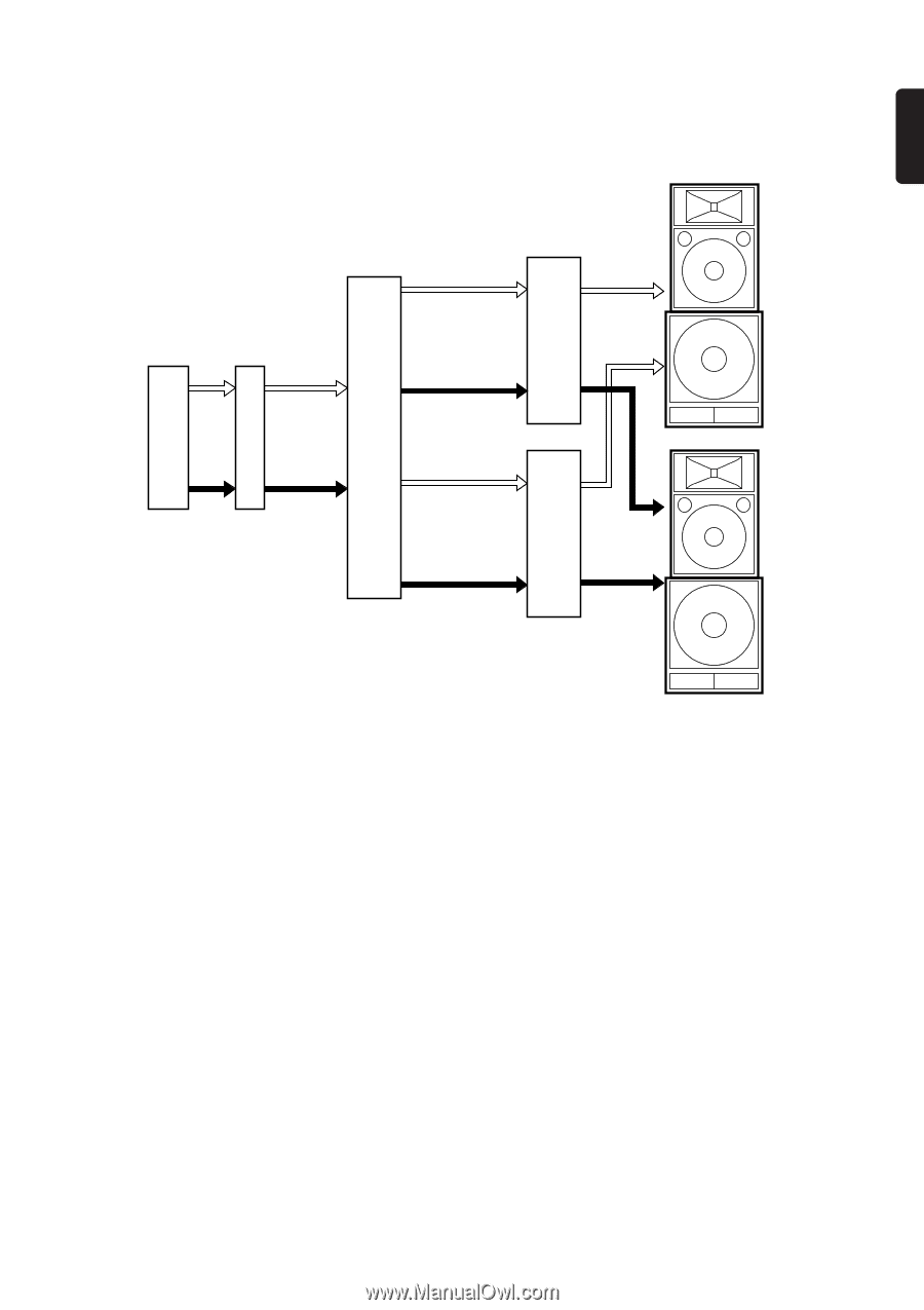
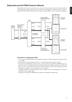
ENGLISH I Subwoofers and the PN90 Crossover Network Adding subwoofers to speaker systems like the one shown in the diagram can provide superior dynamic range and overall sound quality. After dividing the line-level audio from the preamplifier or mixing console into separate frequency bands via the PN90 crossover network, the separate frequency bands are sent to separate power amplifiers. MIXING CONSOLE L R PN90 TWO-CHANNEL POWER AMPLIFIER TWO-CHANNEL GRAPHIC EQUALIZER LEFT HIGH LL INPUT OUTPUT L LEFT INPUTS RIGHT R RIGHT TO POWER AMP INPUTS LEFT RR LL LOW INPUT OUTPUT RIGHT RR TWO-CHANNEL POWER AMPLIFIER SPEAKER SYSTEM SUBWOOFER SPEAKER SYSTEM SUBWOOFER Precautions for operating the PN90 • Do not connect the PN90 between the power amplifier and speakers. The high voltage levels produced can damage the PN90. • Use the PN90 with a load impedance of between 7.5 and 30kΩ. (Rated load impedance is 15kΩ) • The polarity of the LOW signal is inverted at the crossover point between the LOW and HIGH signals. Com- pensate for this by reversing the polarity when connecting the power amplifier output jacks to a subwoofer. Note that you must reverse the polarity between the power amplifier and subwoofers rather than between the PN90 and power amplifier to prevent damage to the connected device. • The PN90's connectors are unbalanced phone jacks. Use shielded audio cable with phone plugs to connect to the PN90. Do not use speaker cable. • Adjust the level of the LOW and HIGH signals using the power amplifier volume controls. 5
-
 1
1 -
 2
2 -
 3
3 -
 4
4 -
 5
5 -
 6
6 -
 7
7 -
 8
8 -
 9
9 -
 10
10 -
 11
11
 |
 |