Yamaha SR-30 SR-30 OWNERS MANUAL - Page 5
Panel, Parts, Their, Functions, W~wnn
 |
View all Yamaha SR-30 manuals
Add to My Manuals
Save this manual to your list of manuals |
Page 5 highlights
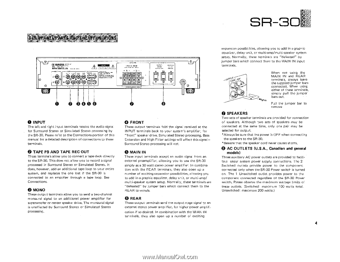
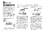
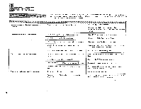
REAR PANEL PARTS AND THEIR FUNCTIONS *_YAMAHA=" NIPPOK GAKKI CO.,LTO. cd) a ta) our CO) ro) (6) ATTENTION:, os Eamp:inErnana W~wnnWrirgria eu 5.T- AKERS +ll - -0 + ail ] •f*J wami CLRLCIS G20,41. Cava:, a O a O O 4 0 O INPUT The left and right input terminals receive the audio signal for Surround Stereo or Simulated Stereo processing by the SR-30. Please refer to the Connections portion of this manual for a detailed description of connections to these terminals. OD TAPE PB AND TAPE REC OUT These terminals allow you to connect a tape deck directly to the SR-30. This does not allow you to record a signal processed in Surround Stereo or Simulated Stereo. It does, however, add an additional tape loop to your entire system, and replaces the one lost if the SR-30 is connected to an amplifier through a tape loop. See Connections. 4) MONO These output terminals allow you to send a two-channel monaural signal to an additional power amplifier for superwoofer or center speaker drive. The monaural signal is unaffected by Surround Stereo or Simulated Stereo processing. (3 FRONT These output terminals fold the signal received at the INPUT terminals back to your system's amplifier, for "front" speaker drive. Simulated Stereo processing, Bass Extension and High Filter settings will affect this signal- Surround Stereo processing will not. 4) MAIN IN These input terminals accept an audio signal from an external preamplifier, allowing you to use the SR-30 simply as a 30 watt stereo power amplifier. In combination with the REAR terminals, they also open up a number of exciting expansion possibilities, allowing you to add in a graphic equal izer, delay unit, or multi-amp/ multi-speaker system setup. Normally, these terminals are "defeated" by jumper bars which connect them to the REAR terminals. REAR These output terminals send the output stage signal to an external stereo power amplifier, for higher power amplification if so desired. In combination with the MI AN IN terminals, they also open up a number of exciting ri g SR 30 _al expansion possibilities, allowing you to add in a graphic equalizer, delay unit, or multi-amp/multi-speaker system setup. Normally, these terminals are "defeated" by jumper bars which connect them to the MAIN IN input terminals. When not using the TP u MAIN IN and REAR terminals, always leave the supplied jumper bars connected. When using either of these terminals, simply pull the jumper bars out. Pul l the jumper bar to remove SPEAKERS Two sets of speaker terminals are provided for connection of speakers. Although two sets of speakers may be connected at the same time, only one pair may be selected for output. *Always be sure that the power is OFF when connecting the speakers to the SR-30. *Beware that the speaker cord never causes shorts. 43 AC OUTLETS (U.S.A., Canadian and general models) Three auxiliary AC power outlets are provided to facilitate easier system power supply connections. The 2 Switched outlets provide power to the component connected only when the SR-30 Power switch is turned on. The 1 Unswitched outlet provides power to the component connected regardless of the SR-30 Power switch. Please observe the maximum wattage limits of these outlets. (Switched: maximum 100 watts total. Unswitched: maximum 200 watts.) 4
-
 1
1 -
 2
2 -
 3
3 -
 4
4 -
 5
5 -
 6
6 -
 7
7 -
 8
8 -
 9
9 -
 10
10 -
 11
11 -
12
 |
 |