Yamaha STUDIO Owners Manual - Page 12
Sw10 Studio
 |
View all Yamaha STUDIO manuals
Add to My Manuals
Save this manual to your list of manuals |
Page 12 highlights
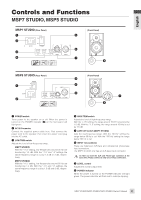
English SW10 STUDIO SW10 STUDIO (Rear Panel) 345 (Front Panel) 6 7 8 1 2 1 POWER switch Turns power to the speaker on or off. When the power is turned on the POWER indicator (8) on the front panel will light green. 2 AC IN Connector Connect the supplied power cable here. First connect the power cord to the subwoofer, then insert the power cord plug into the AC outlet. 3 PHASE switch Selects a phase of output sound from the SW10 STUDIO. You will usually set this switch to "NORM". However, the "REV." setting may improve low-range response, depending on the type and location of the entire speaker system. Try both settings and select the one that produces the best low-end sound. 4 HIGH CUT control Use the HIGH CUT control to set the cutoff frequency of the signal output from the SW10 STUDIO from 40 Hz to 120 Hz. 5 LEVEL control Adjusts the overall output level. 6 INPUT L/R/SUBWOOFER connector These are balanced XLR-type input connectors. Three different signals can be simultaneously input via these connectors. The input signals are mixed before being sent to the subwoofer. 7 OUTPUT L/R/SUBWOOFER connector These XLR-type balanced output connectors output the signals received at the INPUT L/R/SUBWOOFER connectors, respectively. 8 POWER indicator When the power is turned on the POWER indicator will light green. The power indicator will flash red to indicate clipping. 12 MSP7 STUDIO/MSP5 STUDIO/SW10 STUDIO Owner's Manual
-
 1
1 -
2
-
3
-
4
-
5
-
6
-
 7
7 -
 8
8 -
 9
9 -
 10
10 -
 11
11 -
 12
12 -
 13
13 -
 14
14 -
 15
15 -
 16
16
 |
 |
